
Nissan Juke Service and Repair Manual : Back door opener switch
Component Function Check
1.CHECK FUNCTION
1. Select “TRUNK� of “BCM� using CONSULT-III.
2. Select “TR/BD OPEN SW� in “DATA MONITOR� mode.
3. Check that the function operates normally according to the following conditions.

Is the inspection result normal? YES >> Back door opener switch is OK.
NO >> Refer to DLK-69, "Diagnosis Procedure".
Diagnosis Procedure
1.CHECK BACK DOOR OPENER SWITCH INPUT SIGNAL
1. Turn ignition switch OFF.
2. Disconnect back door opener switch connector.
3. Check signal between back door opener switch harness connector and ground using oscilloscope.
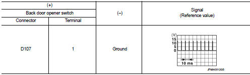
Is the inspection result normal? YES >> GO TO 3.
NO >> GO TO 2.
2.CHECK BACK DOOR OPENER SWITCH CIRCUIT
1. Disconnect BCM connector.
2. Check continuity between BCM harness connector and back door opener switch harness connector.

3. Check continuity between BCM harness connector and ground.

Is the inspection result normal? YES >> Replace BCM. Refer to BCS-93, "Removal and Installation".
NO >> Repair or replace harness.
3.CHECK BACK DOOR OPENER SWITCH GROUND CIRCUIT
Check continuity between back door opener switch harness connector and ground.

Is the inspection result normal? YES >> GO TO 4.
NO >> Repair or replace harness.
4.CHECK BACK DOOR OPENER SWITCH
Refer to DLK-70, "Component Inspection".
Is the inspection result normal? YES >> GO TO 5.
NO >> Replace back door opener switch.
5.CHECK INTERMITTENT INCIDENT
Refer to GI-42, "Intermittent Incident".
>> INSPECTION END
Component Inspection
1.CHECK BACK DOOR OPENER SWITCH
1. Turn ignition switch OFF.
2. Disconnect back door opener switch connector.
3. Check continuity between back door opener switch terminals.

Is the inspection result normal? YES >> INSPECTION END
NO >> Replace back door opener switch.
 Back door opener actuator
Component Function Check
1.CHECK FUNCTION
1. Select “INTELLIGENT KEY� of “BCM� using CONSULT-III.
2. Select “TRUNK/BACK DOOR� in “ACTIVE TEST� mode.
3. Check that the function oper ...
 Back door request switch
Component Function Check
1.CHECK FUNCTION
1. Select “INTELLIGENT KEY� of “BCM� using CONSULT-III.
2. Select “REQ SW-BD/TR� in “DATA MONITOR� mode.
3. Check that the function operat ...
Other materials:
Fog light switch (if so equipped)
To turn the fog lights on, turn the headlight switch to the
position, then turn the switch to the
position. To turn them off, turn the
switch to the OFF position.
The headlights must be on for the fog lights to operate.
When the headlight switch is in the AUTO position, turning the fog lig ...
Upper link
Exploded View
1. Rear suspension member
2. Adjusting bolt
3. Upper link
4. Eccentric disk
5. Lower link
6. Suspension arm bracket
7. Suspension arm
: Vehicle front
: Always replace after every
disassembly.
: N·m (kg-m, ft-lb)
Removal and Installation
REMOVAL
1. Remove tires. WT ...
Back door finisher
Exploded View
1. Rear view camera
2. Back door opener request switch
3. Emblem
4. Back door finisher
: Clip
: Pawl
: Do not reuse
Removal and Installation
REMOVAL
1. Remove back door trim. Refer to INT-35, "BACK DOOR LOWER FINISHER :
Removal and Installation".
2. Remove ba ...
