Nissan Juke Service and Repair Manual : Liquid Gasket
REMOVAL OF LIQUID GASKET
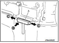
ŌĆó After removing mounting nuts and bolts, separate the mating surface using the seal cutter [SST: KV10111100] (A) and remove old liquid gasket sealing.
CAUTION:
Be careful not to damage the mating surfaces.
ŌĆó Tap the seal cutter [SST: KV10111100] to insert it (B), and then slide it (C) by tapping on the side as shown in the figure.
ŌĆó In areas where the seal cutter [SST: KV10111100] is difficult to use, lightly tap the parts using a plastic hammer to remove it.
CAUTION:
If for some unavoidable reason tool such as a screwdriver is
used, be careful not to damage the mating surfaces.
LIQUID GASKET APPLICATION PROCEDURE
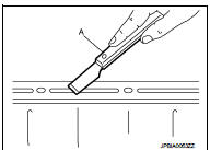
1. Using a scraper (A), remove old liquid gasket adhering to the liquid gasket application surface and the mating surface.
ŌĆó Remove liquid gasket completely from the groove of the liquid gasket application surface, mounting bolts, and bolt holes.
2. Wipe the liquid gasket application surface and the mating surface with white gasoline (lighting and heating use) to remove adhering moisture, grease and foreign materials.
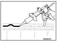
3. Attach liquid gasket tube to the tube presser (commercial service tool).
Use Liquid Gasket or equivalent.
4. Apply liquid gasket without gaps to the specified location according to the specified dimensions.
ŌĆó If there is a groove for liquid gasket application, apply liquid gasket to the groove.
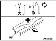
ŌĆó As for bolt holes (B), normally apply liquid gasket inside the holes. Occasionally, it should be applied outside the holes.
Check to read the text of this manual.
A : Groove
: Inside
ŌĆó Within five minutes of liquid gasket application, install the mating component.
ŌĆó If liquid gasket protrudes, wipe it off immediately.
ŌĆó Do not retighten mounting bolts or nuts after the installation.
ŌĆó After 30 minutes or more have passed from the installation, fill engine oil and engine coolant.
CAUTION:
If there are specific instructions in this manual, observe them.
 Precaution
...

Other materials:
Precaution for Supplemental Restraint System (SRS) "AIR BAG" and "SEAT BELT
PRE-TENSIONER"
The Supplemental Restraint System such as ŌĆ£AIR BAGŌĆØ and ŌĆ£SEAT BELT PRE-TENSIONERŌĆØ,
used along
with a front seat belt, helps to reduce the risk or severity of injury to the
driver and front passenger for certain
types of collision. Information necessary to service the system safely is
...
Parking/parking on hills
WARNING
ŌĆó Do not stop or park the vehicle over flammable materials such as dry grass,
waste paper or rags. They may ignite and cause a fire.
ŌĆó Never leave the engine running while the vehicle is unattended.
ŌĆó Do not leave children unattended inside the vehicle. They could unknowingly ac ...
B1179 lap Pre-tensioner RH
DTC Logic
DTC CONFIRMATION PROCEDURE
1.CHECK SELF-DIAGNOSTIC RESULT
With CONSULT-III
1. Turn ignition switch ON.
2. Perform ŌĆ£Self Diagnostic ResultŌĆØ mode of ŌĆ£AIR BAGŌĆØ using CONSULT-III.
Without CONSULT-III
1. Turn ignition switch ON.
2. Check the air bag warning lamp status. Refe ...
