Nissan Juke Service and Repair Manual : B2628 outside antenna
DTC Logic
DTC DETECTION LOGIC
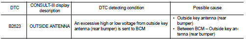
DTC CONFIRMATION PROCEDURE
1.PERFORM DTC CONFIRMATION PROCEDURE
1. Disconnect outside key antenna (rear bumper) connector.
2. Perform ÔÇťINTELLIGENT KEYÔÇŁ Self Diagnostic Result.
Is outside key antenna DTC detected? YES >> Refer to DLK-65, "Diagnosis Procedure".
NO >> Outside key antenna (rear bumper) is OK.
Diagnosis Procedure
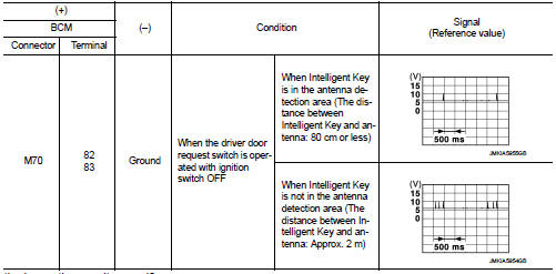
1.CHECK OUTSIDE KEY ANTENNA INPUT SIGNAL 1
1. Turn ignition switch OFF.
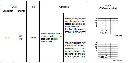
2. Check signal between BCM harness connector and ground using oscilloscop
Is the inspection result normal? YES >> Replace BCM. Refer to BCS-93, "Removal and Installation".
NO >> GO TO 2.
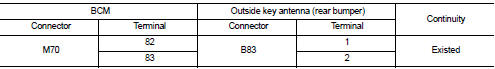
2.CHECK OUTSIDE KEY ANTENNA CIRCUIT
1. Disconnect BCM connector and outside key antenna (rear bumper) connector.
2. Check continuity between BCM harness connector and outside key antenna (rear bumper) harness connector.
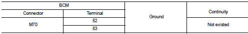
3. Check continuity between BCM harness connector and ground.
Is the inspection result normal? YES >> GO TO 3.
NO >> Repair or replace harness.
3.CHECK OUTSIDE KEY ANTENNA INPUT SIGNAL 2
1. Replace outside key antenna (rear bumper). (New antenna or other
antenna)
2. Connect BCM and outside key antenna (rear bumper) connector.
3. Check signal between BCM harness connector and ground using oscilloscope.
Is the inspection result normal? YES >> Replace outside key antenna (rear bumper).
NO >> Replace BCM. Refer to BCS-93, "Removal and Installation".
 B2627 outside antenna
DTC Logic
DTC DETECTION LOGIC
DTC CONFIRMATION PROCEDURE
1.PERFORM DTC CONFIRMATION PROCEDURE
1. Disconnect outside key antenna (passenger side) connector.
2. Perform ÔÇťINTELLIGENT KEYÔÇŁ Self ...
 Back door opener actuator
Component Function Check
1.CHECK FUNCTION
1. Select ÔÇťINTELLIGENT KEYÔÇŁ of ÔÇťBCMÔÇŁ using CONSULT-III.
2. Select ÔÇťTRUNK/BACK DOORÔÇŁ in ÔÇťACTIVE TESTÔÇŁ mode.
3. Check that the function oper ...
Other materials:
Jump starting
If the 12-volt auxiliary system in your Nissan Leaf requires a boost to activate, follow the procedures and safety precautions outlined below. Please understand that jump starting is intended solely to provide the necessary power to operate the vehicle's electrical control systems, which in turn all ...
Diagnosis and repair work flow
Flowchart of Trouble Diagnosis
NOTE:
ÔÇťDTCÔÇŁ includes DTC at the 1st trip.
1.OBTAIN INFORMATION ABOUT SYMPTOM
1. Refer to TM-372, "Question sheet" and interview the customer to obtain the
malfunction information (conditions
and environment when the malfunction occurred) as much ...
Seat belt maintenance
ÔÇó To clean the seat belt webbing, apply a mild soap solution or any solution
recommended for cleaning upholstery or carpets.
Then wipe with a cloth and allow the seat belts to dry in the shade. Do not allow
the seat belts to retract until they are completely dry.
ÔÇó If dirt builds up in the ...
