Nissan Juke Service and Repair Manual : Automatic speed control device (ASCD)
Automatic speed control device (ASCD) : System Diagram
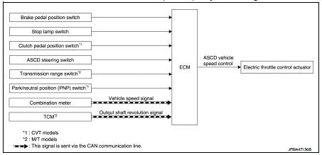
Automatic speed control device (ASCD) : System Description
INPUT/OUTPUT SIGNAL CHART
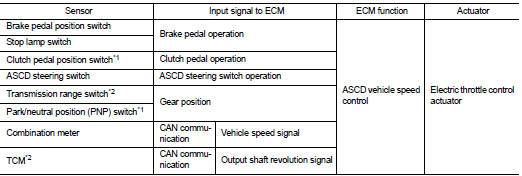
*1: M/T models
*2: CVT models
BASIC ASCD SYSTEM
Refer to Owner's Manual for ASCD operating instructions.
Automatic Speed Control Device (ASCD) allows a driver to keep vehicle at predetermined constant speed without depressing accelerator pedal. Driver can set vehicle speed in advance between approximately 40 km/ h (25 MPH) and 194 km/h (120 MPH).
ECM controls throttle angle of electric throttle control actuator to regulate engine speed.
Operation status of ASCD is indicated by CRUISE indicator and SET indicator in combination meter. If any malfunction occurs in ASCD system, it automatically deactivates control.
Refer to EC-69, "AUTOMATIC SPEED CONTROL DEVICE (ASCD) : Switch Name and Function" for ASCD operating instructions.
NOTE
:
Always drive vehicle in safe manner according to traffic conditions and obey all
traffic laws.
 Evaporative emission system
Evaporative emission system: System
Diagram
Evaporative emission system : System
Description
INPUT/OUTPUT SIGNAL CHART
*: ECM determines the start signal status by the signals of engine spee ...
 Speed limiter
Speed limiter : System Diagram
Speed limiter : System Description
INPUT/OUTPUT SIGNAL CHART
*: This signal is sent to the ECM through CAN communication line
BASIC SPEED LIMITER SYSTEM
• Sp ...
Other materials:
LAN System can system (type 5)
DTC/CIRCUIT DIAGNOSIS
Main line between IPDM-E and DLC circuit
Diagnosis Procedure
1.CHECK CONNECTOR
1. Turn the ignition switch OFF.
2. Disconnect the battery cable from the negative terminal.
3. Check the following terminals and connectors for damage, bend and loose
connection (connector s ...
ICC system limitations
WARNING
The following points outline the operational boundaries of the Intelligent Cruise Control (ICC) system. Operating your Nissan Leaf without regard for these limitations can lead to a serious accident, resulting in injury or death:
The ICC system is optimized for travel on ...
B2098 ignition relay on stuck
Description
• IPDM E/R operates the ignition relay when it receives an ignition switch ON
signal from BCM via CAN communication.
• Turn the ignition relay OFF by pressing the push-button ignition switch once
when the vehicle speed is 4 km/
h (2.5 MPH) or less.
• Turn the ignition relay ...
