Nissan Juke Service and Repair Manual : Speed limiter
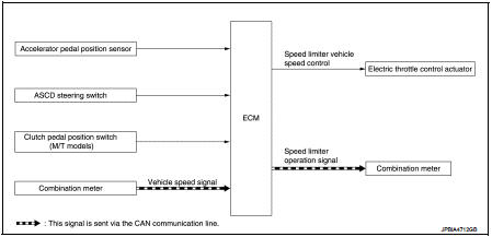
Speed limiter : System Diagram
Speed limiter : System Description
INPUT/OUTPUT SIGNAL CHART
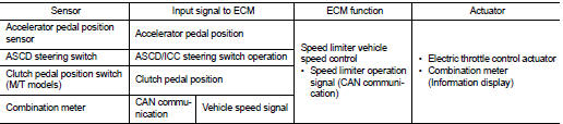
*: This signal is sent to the ECM through CAN communication line
BASIC SPEED LIMITER SYSTEM
• Speed limiter is a system that enables to restrict the vehicle speed within the set speed that is selected by the driver. Driver can be set the vehicle speed in the set speed range.
• ECM controls throttle angle of electric throttle control actuator to regulate vehicle speed.
• Operation status of speed limiter is indicated on the information display in the combination meter.
• If any malfunction occurs in speed limiter system, it automatically deactivates the speed limiter control.
Refer to EC-70, "SPEED LIMITER : Switch Name and Function" for speed limiter operating instructions.
CAUTION:
Always drive vehicle in safe manner according to traffic conditions and obey all
traffic laws.
NOTE:
Since the speed limiter is controlled by the electric throttle control actuator, vehicle speed may exceed a set speed during downhill driving.
 Automatic speed control device (ASCD)
Automatic speed control device (ASCD)
: System Diagram
Automatic speed control device (ASCD)
: System Description
INPUT/OUTPUT SIGNAL CHART
*1: M/T models
*2: CVT models
BASIC ASCD SYSTEM
...
 NISSAN dynamic control system
NISSAN dynamic control system : System
Diagram
CVT models
M/T models
NISSAN dynamic control system : System
Description
CVT models
System Description
TCM transmits a drive mode select sig ...
Other materials:
B1147 curtain air bag module RH
DTC Logic
DTC DETECTION LOGIC
DTC CONFIRMATION PROCEDURE
1.CHECK SELF-DIAG RESULT
With CONSULT-III
1. Turn ignition switch ON.
2. Perform “Self Diagnostic Result” mode of “AIR BAG” using CONSULT-III.
Without CONSULT-III
1. Turn ignition switch ON.
2. Check the air bag warning la ...
Rear shock absorber
Exploded View
1. Rear suspension beam
2. Shock absorber
3. Bound bumper
4. Bound bumper cover
5. Washer
6. Bushing
7. Distance tube
8. Piston rod lock nut
9. Cap
: Always replace after every
disassembly.
: N·m (kg-m, ft-lb)
Removal and Installation
REMOVAL
1. Remove tires. R ...
Front seat (2WD)
Exploded View
DRIVER SEAT
LHD models
1. Headrest
2. Headrest holder (locked)
3. Headrest holder (free)
4. Seatback heater unit
5. Inner lower cover
6. Seatback trim
7. Seatback pad
8. Seat cushion inner finisher
9. Reclining device inner cover
10. Anchor bolt
11. Seat belt buck ...
