Nissan Juke Service and Repair Manual : NISSAN dynamic control system
NISSAN dynamic control system : System Diagram
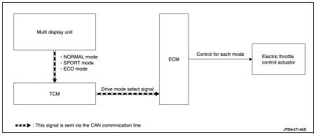
CVT models
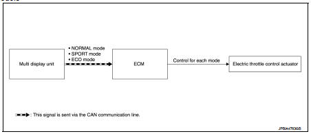
M/T models
NISSAN dynamic control system : System Description
CVT models
System Description
TCM transmits a drive mode select signal to ECM via CAN communication, according
to a NORMAL mode
signal, SPORT mode signal, or ECO mode signal received from the multi display
unit via CAN communication.
ECM controls torque and throttle opening angle characteristics appropriate for each mode, based on a received drive mode select signal.
NOTE
:
• Because of the multi display unit operation, the display may indicate that the
mode is switching. However,
the mode may not actually switch due to CAN communication error.
• When a CAN communication error occurs between ECM and TCM, the mode switches to NORMAL mode.
M/T models
System Description
ECM controls torque and throttle opening angle characteristics appropriate for
each mode, based on a NORMAL
mode signal, SPORT mode signal, or ECO mode signal received from the multi
display unit via CAN
communication.
NOTE
:
• Because of the multi display unit operation, the display may indicate that the mode is switching. However, the mode may not actually switch due to CAN communication error.
• When a CAN communication error occurs between ECM and the multi display unit, the mode switches to NORMAL mode.
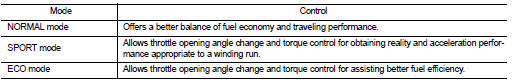
Control By Mode
 Speed limiter
Speed limiter : System Diagram
Speed limiter : System Description
INPUT/OUTPUT SIGNAL CHART
*: This signal is sent to the ECM through CAN communication line
BASIC SPEED LIMITER SYSTEM
• Sp ...
 Can communication
CAN COMMUNICATION : System Description
CAN (Controller Area Network) is a serial communication line for real time
application. It is an on-vehicle multiplex
communication line with high data commu ...
Other materials:
Component parts
Component Parts Location
ENGINE ROOM COMPARTMENT
Top View
1. Priming pump
2. Turbocharger boost control solenoid
valve
3. Cooling fan motor
4. Refrigerant pressure sensor
5. IPDM E/R
6. ECM
7. Mass air flow sensor (with intake air
temperature sensor)
8. Electric throttle control act ...
Maintenance schedules
To guarantee the long-term reliability, safety, and operational economy of your vehicle, NISSAN provides two distinct maintenance schedules tailored to your specific driving habits. These structured plans cover both distance and time-based intervals, extending up to 120,000 miles (192,000 km) or 96 ...
P1550 battery current sensor
DTC Logic
DTC DETECTION LOGIC
DTC CONFIRMATION PROCEDURE
1.PRECONDITIONING
If DTC Confirmation Procedure has been previously conducted, always perform
the following before conducting
the next test.
1. Turn ignition switch OFF and wait at least 10 seconds.
2. Turn ignition switch ON.
3. ...
