Nissan Juke Service and Repair Manual : U1000 can comm
Description
CAN (Controller Area Network) is a serial communication line for real time applications. It is an on-vehicle multiplex communication line with high data communication speed and excellent error detection ability. Modern vehicle is equipped with many electronic control unit, and each control unit shares information and links with other control units during operation (not independent). In CAN communication, control units are connected with 2 communication lines (CAN H-line, CAN L-line) allowing a high rate of information transmission with less wiring. Each control unit transmits/receives data but selectively reads required data only.
CAN Communication Signal Chart. Refer to LAN-31, "CAN COMMUNICATION SYSTEM : CAN Communication Signal Chart".
DTC Logic
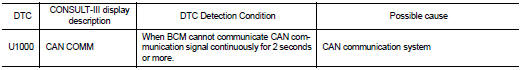
DTC DETECTION LOGIC
Diagnosis Procedure
1.PERFORM SELF DIAGNOSTIC
1. Turn ignition switch ON and wait for 2 seconds or more.
2. Check ŌĆ£Self Diagnostic ResultŌĆØ of BCM.
Is DTC ŌĆ£U1000ŌĆØ displayed? YES >> Refer to LAN-17, "Trouble Diagnosis Flow Chart".
NO >> Refer to GI-42, "Intermittent Incident".

 U1010 control unit (can)
DTC Logic
DTC DETECTION LOGIC
Diagnosis Procedure
1.REPLACE BCM
When DTC ŌĆ£U1010ŌĆØ is detected, replace BCM.
>> Replace BCM. Refer to BCS-93, "Removal and Installation". ...
Other materials:
Precaution for Supplemental Restraint System (SRS) "AIR BAG" and "SEAT BELT
PRE-TENSIONER"
The Supplemental Restraint System such as ŌĆ£AIR BAGŌĆØ and ŌĆ£SEAT BELT PRE-TENSIONERŌĆØ,
used along
with a front seat belt, helps to reduce the risk or severity of injury to the
driver and front passenger for certain
types of collision. Information necessary to service the system safely is
...
Removal and installation
COMBINATION METER
Exploded View
REMOVAL
Refer to IP-12, "Exploded View".
DISASSEMBLY
1. Front cover
2. Unified meter control unit
Removal and Installation
REMOVAL
1. Remove cluster lid A. Refer to IP-13, "Removal and Installation".
2. Remove the mounting screws of ...
P0850 PNP switch
Description
For CVT models, transmission range switch is turn ON when the selector lever
is P or N.
For M/T models, park/neutral position (PNP) range switch is ON when the selector
lever is Neutral position.
ECM detects the position because the continuity of the line (the ON) exists.
DTC ...
