Nissan Juke Service and Repair Manual : Door motor
Exploded View
LEFT SIDE
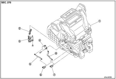
1. A/C unit assembly
2. Intake door lever
3. Intake door motor
4. Air mix door motor
5. Upper air mix door rod
6. Upper air mix door lever
7. Lower air mix door lever
8. Lower air mix door rod
RIGHT SIDE
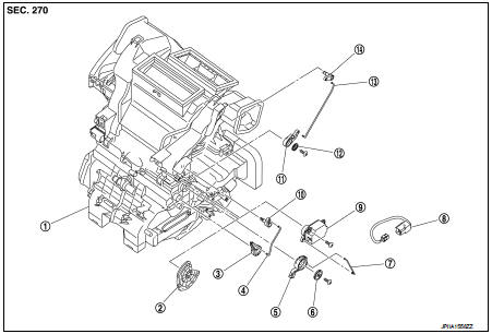
1. A/C unit assembly
2. Main link
3. Sub defroster door link
4. Sub defroster door rod
5. Mode link
6. Plate
7. Mode link rod
8. Sub harness
9. Mode door motor
10. Sub defroster door lever
11. Center ventilator and defroster door link
12. Plate
13. Center ventilator and defroster door rod
14. Center ventilator and defroster door lever
Intake door motor : Removal and Installation
REMOVAL
1. Remove instrument lower panel LH. Refer to IP-13, "Removal and
Installation". (LHD models)
2. Remove glove box assembly. Refer to IP-13, "Removal and Installation". (RHD
models)
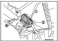
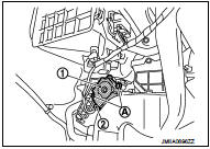
3. Remove fixing screws (A), and then remove intake door motor
(1) from A/C unit assembly.
4. Disconnect intake door motor connector (2).
INSTALLATION
Install in the reverse order of removal.
Mode door motor : Removal and Installation
REMOVAL
1. Remove glove box assembly Refer to IP-13, "Removal and Installation". (LHD
models)
2. Remove instrument lower panel RH. Refer to IP-13, "Removal and Installation".
(RHD models)
3. Remove foot duct RH. Refer to VTL-14, "FOOT DUCT : Removal and
Installation".
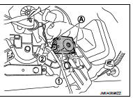
4. Disconnect mode link rod from mode door motor.
5. Remove fixing screws (A), and then remove mode door motor (1).
6. Disconnect mode door motor connector (2).
INSTALLATION
Install in the reverse order of removal.
Air mix door motor : Removal and Installa
REMOVAL
1. Remove instrument lower panel LH. Refer to IP-13, "Removal and
Installation". (LHD models)
2. Remove glove box assembly. Refer to IP-13, "Removal and Installation". (RHD
models)
3. Remove fixing screws (A), and then remove air mix door motor
(1) from A/C unit assembly.
4. Disconnect air mix door motor connector (2).
INSTALLATION Install in the reverse order of removal.
 Power transistor
Exploded View
1. A/C unit assembly
2. Blower fan resistor*1
3. Sub harness*1
4. Power transistor*2
5. Sub harness*2
6. Blower motor
• *1: Manual air conditioner
• *2: Automatic air c ...

Other materials:
Key interlock cable
Exploded View
1. CVT shift selector assembly
2. Key interlock cable
A: Key cylinder
B: Clip
C: Clip
Removal and Installation
REMOVAL
CAUTION:
Always apply the parking brake before performing removal and installation.
1. Shift the selector lever to the “P” position.
2. Remove the ...
Brake piping
Front : Exploded View
WITHOUT ESP
1. Brake booster
2. Master cylinder assembly
3. Brake tube
4. Connector bracket
5. Connector
6. ABS actuator and electric unit (control
unit)
7. Lock plate
8. Brake hose
9. Union bolt
10. Copper washer
A. To rear brake tube
: N·m (kg-m, ft-lb) ...
Seats, seat belts and Supplemental Restraint System (SRS)
1. Rear head restraints
2. Child restraint anchor points (for top tether strap child restraint)
3. Front head restraints
— Front-seat Active Head Restraints
4. Roof-mounted curtain side-impact supplemental air bags
5. Seat belts
6. Front seats
7. Supplemental front-impact air bags ...
