Nissan Juke Service and Repair Manual : Removal and installation
HORN
Exploded View
WITHOUT VEHICLE SECURITY SYSTEM
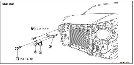
1. Horn high
2. Horn low
3. Horn bracket
WITH VEHICLE SECURITY SYSTEM
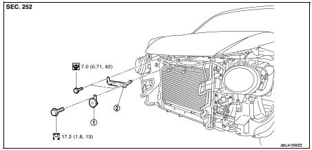
1. Horn low
2. Horn bracket
Removal and Installation
REMOVAL
Without Vehicle Security System 1. Remove the front center grille and front side grille (LH/RH). Refer to EXT-18, "Removal and Installation".
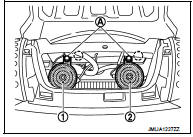
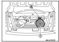
2. Disconnect the horn (high and low) connectors.
3. Remove the horn mounting bolts (A). Remove the horn high (1) and horn low (2).
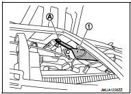
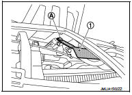
4. Remove harness fixing clip from horn bracket.
 : Harness fixing clip
5. Remove horn bracket mounting bolts (LH/RH). Remove horn bracket (1) from radiator core support upper.
With Vehicle Security System 1. Remove the front center grille and front side grille (LH/RH). Refer to EXT-18, "Removal and Installation".
2. Disconnect the horn low connectors.
3. Remove the horn mounting bolt (A). Remove the horn low (1).
4. Remove harness fixing clip from horn bracket.
 : Harness fixing clip
5. Remove horn bracket mounting bolts (LH/RH). Remove horn bracket (1) from radiator core support upper.
INSTALLATION
Install in the reverse order of removal.
 Wiring diagram
HORN
Wiring Diagram
For connector terminal arrangements, harness layouts, and alphabets in a
(option abbreviation; if not
described in wiring diagram), refer to GI-12, "Connector Information/ ...
 Power Outlet
...
Other materials:
Rear window defogger on signal
With auto A/C
WITH AUTO A/C : Description
Turns the indicator lamp in the rear window defogger switch ON when operating
the rear window defogger
WITH AUTO A/C : Component Function Check
1.CHECK REAR WINDOW DEFOGGER ON SIGNAL
Check that the indicator lamp of rear window defogger switch is illu ...
Air cleaner and air duct
Exploded View
1. Turbocharger air inlet pipe
2. Clamp
3. Air duct (suction)
4. Air mass flow sensor
5. O-ring
6. Air duct (inlet)
7. Grommet
8. Air cleaner case
9. Air cleaner filter
10. Cover
11. Holder
A. : To turbocharger
: Vehicle front
: N·m (kg-m, in-lb)
: Always repla ...
P2A00 A/F sensor 1
DTC Logic
DTC DETECTION LOGIC
To judge the malfunction, the A/F signal computed by ECM from the A/F sensor
1 signal is monitored so it will
not shift to LEAN side or RICH side.
DTC CONFIRMATION PROCEDURE
1.PRECONDITIONING
If DTC Confirmation Procedure has been previously conducted, always ...
