Nissan Juke Service and Repair Manual : Wiring diagram
HORN
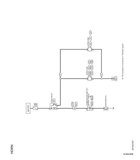
Wiring Diagram
For connector terminal arrangements, harness layouts, and alphabets in a
 (option abbreviation; if not
described in wiring diagram), refer to GI-12, "Connector Information/Explanation
of Option Abbreviation".
 Precaution
Precaution for Supplemental Restraint System (SRS) "AIR BAG" and "SEAT
BELT
PRE-TENSIONER"
The Supplemental Restraint System such as “AIR BAG” and “SEAT BELT
PRE-TENSIO ...
 Removal and installation
HORN
Exploded View
WITHOUT VEHICLE SECURITY SYSTEM
1. Horn high
2. Horn low
3. Horn bracket
WITH VEHICLE SECURITY SYSTEM
1. Horn low
2. Horn bracket
Removal and Installation
REMOVAL
...
Other materials:
Checking engine coolant level
Check the coolant level in the reservoir when the engine is cold. If the coolant
level is below the MIN level 2 , open the reservoir cap and add coolant up to the
MAX level 1 . If the reservoir is empty, check the coolant level in the radiator
when the engine is cold. If there is insufficien ...
Wiring diagram
CHARGING SYSTEM
Wiring Diagram
GASOLINE ENGINE MODELS
For connector terminal arrangements, harness layouts, and alphabets in a
(option abbreviation; if not
described in wiring diagram), refer to GI-12, "Connector Information/Explanation
of Option Abbreviation".
DIESEL ENGINE MOD ...
Diagnosis system (IPDM E/R)
With intelligent key
WITH INTELLIGENT KEY : Diagnosis Description
AUTO ACTIVE TEST
Description
In auto active test mode, the IPDM E/R sends a drive signal to the following
systems to check their operation.
• Oil pressure warning lamp (only for K9K engine models)
• Rear window defogger
...
