Nissan Juke Service and Repair Manual : Front regulator
Exploded View
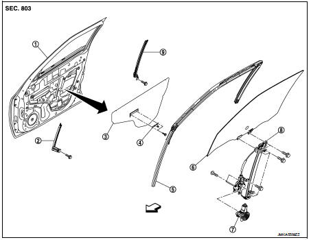
1. Front door panel
2. Lower sash (front)
3. Sealing screen
4. Pull handle bracket
5. Front door glass run
6. Front door glass
7. Power window motor
8. Front door regulator assembly
9. Lower sash (rear)
 : Vehicle fro
Removal and Installation
REMOVAL
1. Remove the front door glass. Refer to GW-17, "Removal and Installation".
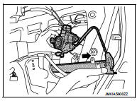
2. Disconnect the power window motor harness connector and harness fixing clip.
3. Remove the regulator assembly mounting bolts.
4. Remove the regulator assembly from the door panel as shown in the figure.
INSTALLATION
Install in the reverse order of removal.
Disassembly and Assembly
DISASSEMBLY
Remove the power window motor from the regulator assembly.
INSPECTION AFTER REMOVAL
Check the regulator assembly for the following items. Replace or grease it if a malfunction is detected.
• Wire wear
• Regulator deformation
ASSEMBLY
Assemble in the reverse order of disassembly.
Inspection and Adjustment
SYSTEM INITIALIZATION
Initialize the system if any of the following work is complete. Refer to PWC-14, "Description".
FITTING INSPECTION
• Check that the glass is fit securely into the sash groove.
• Lower the glass slightly [approximately 10 to 20 mm (0.394 to 0.787 in)], and check that the clearance to the sash is parallel. Loosen the regulator mounting bolts, guide rail mounting bolts, and glass and guide rail mounting bolts to correct the glass position if the clearance between the glass and sash is not parallel.
 Front door glass
Exploded View
1. Front door panel
2. Lower sash (front)
3. Sealing screen
4. Pull handle bracket
5. Front door glass run
6. Front door glass
7. Power window motor
8. Front door regulato ...
 Rear door glass
Exploded View
1. Rear door panel
2. Sealing screen
3. Lower sash (front)
4. Rear door regulator assembly
5. Power window motor
6. Rear door glass
7. Lower sash (rear)
8. Rear door glass ...
Other materials:
P0327, P0328 KS
DTC Logic
DTC DETECTION LOGIC
DTC CONFIRMATION PROCEDURE
1.PRECONDITIONING
If DTC Confirmation Procedure has been previously conducted, always perform
the following procedure
before conducting the next test.
1. Turn ignition switch OFF and wait at least 10 seconds.
2. Turn ignition swit ...
General Precautions
• Turn ignition switch OFF and disconnect the battery cable
from the negative terminal before connecting or disconnecting
the CVT assembly harness connector. Because battery
voltage is applied to TCM even if ignition switch is turned
OFF.
• When connecting or disconnecting pin connectors ...
B1150 curtain air bag module LH
DTC Logic
DTC DETECTION LOGIC
DTC CONFIRMATION PROCEDURE
1.CHECK SELF-DIAG RESULT
With CONSULT-III
1. Turn ignition switch ON.
2. Perform “Self Diagnostic Result” mode of “AIR BAG” using CONSULT-III.
Without CONSULT-III
1. Turn ignition switch ON.
2. Check the air bag warning la ...
