Nissan Juke Service and Repair Manual : Rear door glass
Exploded View
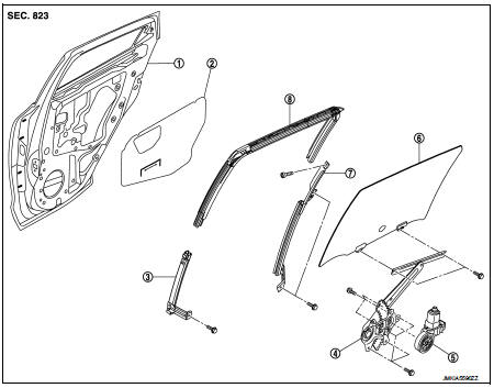
1. Rear door panel
2. Sealing screen
3. Lower sash (front)
4. Rear door regulator assembly
5. Power window motor
6. Rear door glass
7. Lower sash (rear)
8. Rear door glass run
Removal and Installation
REMOVAL
1. Fully open rear door glass.
2. Remove rear door finisher. Refer to INT-16, "Removal and Installation".
3. Remove rear door speaker harness connector and the remove the sealing screen.
NOTE
:
Cut the butyl-tape so that some parts of the butyl-tape do not remain on the
sealing screen, if the sealing
screen is reused.
4. Remove the rear door outside molding.
5. Remove rear door glass run.
6. Operate the power window main switch or regulator handle to raise or lower the door window until the glass mounting bolts can be seen.
7. Remove rear door glass mounting bolts.
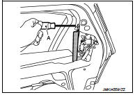
8. Remove lower sash (rear) mounting bolts and TORX bolt with a screwdriver (A) as shown in the figure.
9. Remove lower sash (rear) from the rear door panel.
CAUTION:
Avoid contact between lower sash (rear) and rear door glass when removing.
10. Remove rear door glass from the rear panel.
INSTALLATION
Install in the reverse order of removal.
Inspection and Adjustment
SYSTEM INITIALIZATION
Initialize the system if any of the following work is complete. Refer to PWC-14, "Description".
FITTING INSPECTION
• Check that the glass is fit securely into the sash groove.
• Lower the glass slightly [approximately 10 to 20 mm (0.394 to 0.787 in)], and check that the clearance to the sash is parallel. Loosen the regulator mounting bolts, guide rail mounting bolts, and glass and guide rail mounting bolts to correct the glass position if the clearance between the glass and sash is not parallel.
 Front regulator
Exploded View
1. Front door panel
2. Lower sash (front)
3. Sealing screen
4. Pull handle bracket
5. Front door glass run
6. Front door glass
7. Power window motor
8. Front door regulato ...
 Rear regulator
Exploded View
1. Rear door panel
2. Sealing screen
3. Lower sash (front)
4. Rear door regulator assembly
5. Power window motor
6. Rear door glass
7. Lower sash (rear)
8. Rear door glass ...
Other materials:
Owner’s Manual Supplement 2014 Nissan Juke
The information contained within this supplement replaces the Sun Visors information
contained in Section 3 “Pre-driving checks and adjustments”, the Manual Air Conditioner
(if so equipped) and Automatic Air Conditioner (with Integrated Control System)
information in Section 4 “Heater, a ...
Wiper and washer system
Wiring Diagram - WIPER AND WASHER SYSTEM -
For connector terminal arrangements, harness layouts, and alphabets in a
(option abbreviation; if not
described in wiring diagram), refer to GI-12, "Connector Information/Explanation
of Option Abbreviation".
...
Headlamp aiming system (manual)
Component Inspection
1.CHECK HEADLAMP AIMING SWITCH
1. Remove headlamp aiming switch.
2. Check resistance among each headlamp aiming switch terminal.
Is the inspection result normal?
YES >> Headlamp aiming switch is normal.
NO >> Replace the headlamp aiming switch.
...
