
Nissan Juke Service and Repair Manual : Rear regulator
Exploded View
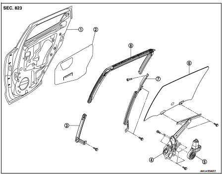
1. Rear door panel
2. Sealing screen
3. Lower sash (front)
4. Rear door regulator assembly
5. Power window motor
6. Rear door glass
7. Lower sash (rear)
8. Rear door glass run
Removal and Installation
REMOVAL
1. Remove rear door glass. Refer to GW-21, "Removal and Installation".
2. Disconnect the power window motor harness connector.
3. Remove rear door regulator mounting bolts and then remove rear door regulator from door panel.
4. Remove lower sash (front) mounting bolt and then remove lower sash (front) from rear door panel.
INSTALLATION
Install in the reverse order of removal.
Disassembly and Assembly
DISASSEMBLY
Remove the power window motor from the regulator assembly.
INSPECTION AFTER REMOVAL
Check the regulator assembly for the following items. Replace or grease it if a malfunction is detected.
• Wire wear
• Regulator deformation
ASSEMBLY
Assemble in the reverse order of disassembly.
Inspection and Adjustment
SYSTEM INITIALIZATION
Initialize the system if any of the following work is complete. Refer to PWC-14, "Description".
FITTING INSPECTION
• Check that the glass is fit securely into the sash groove.
• Lower the glass slightly [approximately 10 to 20 mm (0.394 to 0.787 in)], and check that the clearance to the sash is parallel. Loosen the regulator mounting bolts, guide rail mounting bolts, and glass and guide rail mounting bolts to correct the glass position if the clearance between the glass and sash is not parallel.
 Rear door glass
Exploded View
1. Rear door panel
2. Sealing screen
3. Lower sash (front)
4. Rear door regulator assembly
5. Power window motor
6. Rear door glass
7. Lower sash (rear)
8. Rear door glass ...

Other materials:
Headlamp aiming switch
Exploded View
1. Headlamp aiming switch
2. Instrument lower panel assembly LH
: Pawl
Removal and Installation
REMOVAL
1. Remove instrment lower panel (LH/RH). Refer to IP-13, "Removal and
Installation".
2. Remove headlamp aiming switch fixing clips, and then remove headlamp aim ...
Seats, seat belts and Supplemental Restraint System (SRS)
1. Rear head restraints
2. Child restraint anchor points (for top tether strap child restraint)
3. Front head restraints
— Front-seat Active Head Restraints
4. Roof-mounted curtain side-impact supplemental air bags
5. Seat belts
6. Front seats
7. Supplemental front-impact air bags ...
Water pump
Exploded View
1. Gasket
2. Water pump
3. Water pump pulley
: Always replace after every
disassembly.
: N·m (kg-m, in-lb)
: N·m (kg-m, ft-lb)
Removal and Installation
REMOVAL
1. Drain engine coolant from radiator. Refer to CO-37, "Draining".
CAUTION:
• Perform this st ...
