Nissan Juke Service and Repair Manual : A/C unit assembly
Exploded View (Automatic Air Conditioning)
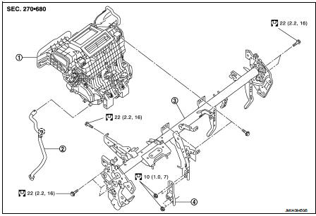
REMOVAL
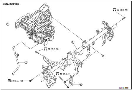
LHD model
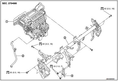
1. A/C unit assembly
2. Drain hose
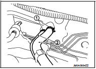
3. Steering member
4. Instrument stay
 : Clip
 : N·m (kg-m, ft-lb)
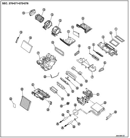
DISASSEMBLY
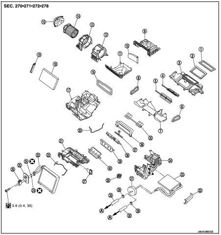
LHD models
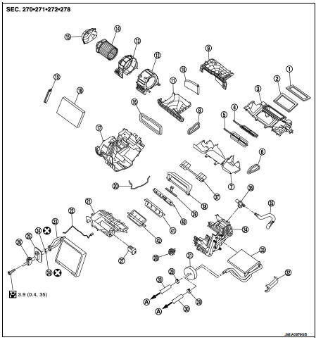
1. Ventilator seal
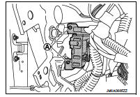
2. Defroster seal
3. Upper attachment case
4. Center ventilator door
5. Defroster door
6. Side ventilator seal LH
7. Lower attachment case
8. Side ventilator seal RH
9. Upper intake case
10. Intake door
11. Lower intake case
12. Blower case LH
13. Blower case RH
14. Blower motor
15. Blower motor cover
16. Intake seal
17. A/C unit case RH
18. Air conditioner filter
19. Filter cover
20. Case packing
21. Evaporator cover
22. Intake sensor
23. Evaporator
24. O-ring
25. Expansion valve grommet
26. Expansion valve
27. Fan control amp.
28. Heater pipe support
29. Clamp
30. Heater hose
31. Heater pipe grommet
32. Heater core side packing
33. Heater core
34. A/C unit case LH
35. Aspirator duct
36. Aspirator
37. Side ventilator door
38. Foot door
39. Center lib case
40. Max. cool door
41. Upper air mix door
42. Lower air mix door
A. To water outlet
 : Do not reuse
 : N·m (kg-m, in-lb)
REMOVAL
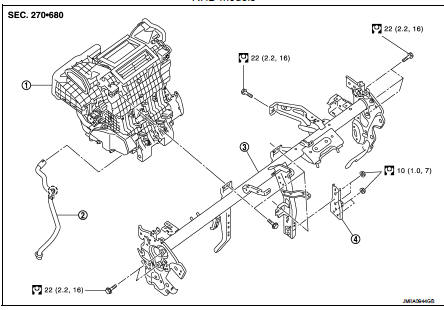
RHD models
1. A/C unit assembly
2. Drain hose
3. Steering member
4. Instrument stay
 : Clip
 : N·m (kg-m, ft-lb)
DISASSEMBLY
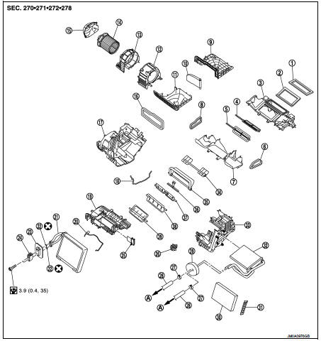
RHD models
1. Ventilator seal
2. Defroster seal
3. Upper attachment case
4. Center ventilator door
5. Defroster door
6. Side ventilator seal LH
7. Lower attachment case
8. Side ventilator seal RH
9. Upper intake case
10. Intake door
11. Lower intake case
12. Blower case LH
13. Blower case RH
14. Blower motor
15. Blower motor cover
16. Intake seal
17. A/C unit case RH
18. Case packing
19. Evaporator cover
20. Intake sensor
21. Evaporator
22. O-ring
23. Expansion valve grommet
24. Expansion valve
25. Fan control amp.
26. Heater pipe support
27. Clamp
28. Heater hose
29. Heater pipe grommet
30. Air conditioner filter
31. Filter cover
32. Heater core
33. A/C unit case LH
34. Aspirator
35. Aspirator duct
36. Side ventilator door
37. Foot door
38. Center lib case
39. Max. cool door
40. Upper air mix door
41. Lower air mix door
A. To water outlet
 : Do not reuse
 : N·m (kg-m, in-lb)
Exploded View (Manual Air Conditioning)
REMOVAL
LHD models
1. A/C unit assembly
2. Drain hose
3. Steering member
4. Instrument stay
 : Clip
 : N·m (kg-m, ft-lb)
DISASSEMBLY
LHD models
1. Ventilator seal
2. Defroster seal
3. Upper attachment case
4. Center ventilator door
5. Defroster door
6. Side ventilator seal LH
7. Lower attachment case
8. Side ventilator seal RH
9. Upper intake case
10. Intake door
11. Lower intake case
12. Blower case LH
13. Blower case RH
14. Blower motor
15. Blower motor cover
16. Intake seal
17. A/C unit case RH
18. Air conditioner filter
19. Filter cover
20. Case packing
21. Evaporator cover
22. Thermo control amp.
23. Evaporator
24. O-ring
25. Expansion valve grommet
26. Expansion valve
27. Blower fan resistor
28. Heater pipe support
29. Clamp
30. Heater hose
31. Heater pipe grommet
32. Heater core side packing
33. Heater core
34. A/C unit case LH
35. Side ventilator door
36. Foot door
37. Center lib case
38. Max. cool door
39. Upper air mix door
40. Lower air mix door
A. To water outlet
 : Do not reuse
 : N·m (kg-m, in-lb)
REMOVAL
RHD models
1. A/C unit assembly
2. Drain hose
3. Steering member
4. Instrument stay
 : Clip
 : N·m (kg-m, ft-lb)
DISASSEMBLY
RHD models
1. Ventilator seal
2. Defroster seal
3. Upper attachment case
4. Center ventilator door
5. Defroster door
6. Side ventilator seal LH
7. Lower attachment case
8. Side ventilator seal RH
9. Upper intake case
10. Intake door
11. Lower intake case
12. Blower case LH
13. Blower case RH
14. Blower motor
15. Blower motor cover
16. Intake seal
17. A/C unit case RH
18. Case packing
19. Evaporator cover
20. Thermo control amp.
21. Evaporator
22. O-ring
23. Expansion valve grommet
24. Expansion valve
25. Blower fan resistor
26. Heater pipe support
27. Clamp
28. Heater hose
29. Heater pipe grommet
30. Air conditioner filter
31. Filter cover
32. Heater core
33. A/C unit case LH
34. Side ventilator door
35. Foot door
36. Center lib case
37. Max. cool door
38. Upper air mix door
39. Lower air mix door
A. To water outlet
 : Do not reuse
 : N·m (kg-m, in-lb)
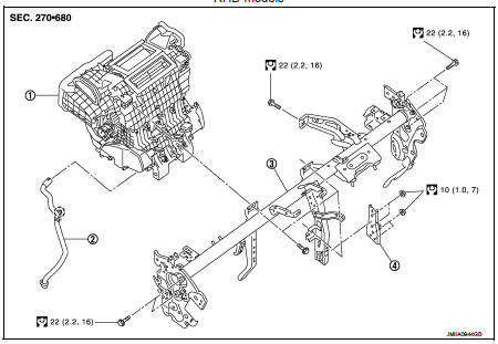
Exploded View (Manual Heater)
REMOVAL
1. A/C unit assembly
2. Drain hose
3. Steering member
4. Instrument stay
 : Clip
 : N·m (kg-m, ft-lb)
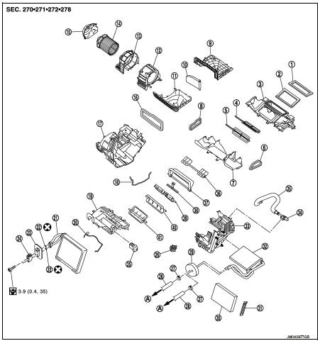
DISASSEMBLY
1. Ventilator seal
2. Defroster seal
3. Upper attachment case
4. Center ventilator door
5. Defroster door
6. Side ventilator seal LH
7. Lower attachment case
8. Side ventilator seal RH
9. Upper intake case
10. Intake door
11. Lower intake case
12. Blower case LH
13. Blower case RH
14. Blower motor
15. Blower motor cover
16. Intake seal
17. A/C unit case RH
18. Air conditioner filter
19. Filter cover
20. Case packing
21. Evaporator cover
22. Dummy evaporator
23. Patch
24. Blower fan resistor
25. Heater pipe support
26. Heater pipe grommet
27. Clamp
28. Heater hose
29. Heater core side packing
30. Heater core
31. A/C unit case LH
32. Side ventilator door
33. Foot door
34. Center lib case
35. Max. cool door
36. Upper air mix door
37. Lower air mix door
A. To water outlet
 : Do not reuse
 : N·m (kg-m, in-lb)
A/C unit assembly : Removal and Installation
CAUTION:
Perform lubricant return operation before each refrigeration system disassembly.
However, if a large
amount of refrigerant or lubricant is detected, never perform lubricant return
operation. Refer to HA-
23, "Perform Lubricant Return Operation".
REMOVAL
1. Use a refrigerant collecting equipment (for HFC-134a) to discharge the refrigerant. Refer to HA-21, "Recycle Refrigerant".
2. Drain engine coolant from cooling system. Refer to CO-37, "Draining".
3. Remove cowl top cover. Refer to EXT-20, "Removal and Installation".
4. Remove air duct. Refer to EM-161, "Removal and Installation".
5. Remove plastic nut, and then move lower dash insulator aside.
 : Plastic nut
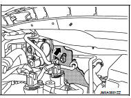
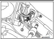
6. Remove mounting bolt (A), and then disconnect low-pressure flexible hose (1) and high-pressure pipe (2) from expansion valve.
CAUTION:
Cap of wrap the joint of the A/C piping and expansion valve
with suitable material such as vinyl tape to avoid the entry
of air.
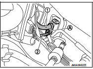
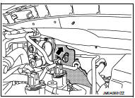
7. Remove clamps (1), and then disconnect heater hose (2) from A/C unit assembly.
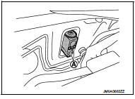
8. Remove rear heater duct 1. Refer to VTL-13, "REAR HEATER DUCT 1 : Removal and Installation". (Only LHD models for cold areas) 9. Disconnect drain hose (1) from A/C unit assembly.
 : Vehicle front
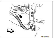
10. Remove instrument panel assembly. Refer to IP-13, "Removal and Installation".
11. Remove side ventirator duct. Refer to VTL-12, "SIDE VENTILATOR DUCT : Removal and Installation".
12. Remove mounting nuts (A), and then remove instrument stay.
 : Vehicle front
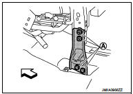
13. Remove J/B fixing screws (A), and then remove J/B.
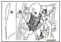
14. Remove BCM fixing screws (A), and then remove BCM.
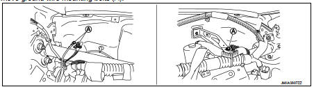
15. Remove ground wire mounting bolts (A).
16. Disconnect the harness connectors and clips required to remove the steering member, and then move the vehicle harness to the position without hindrance for work.
17. Move steering column assembly to a position where it dose not inhibit work.
Refer to ST-10, "Removal
and Installation"
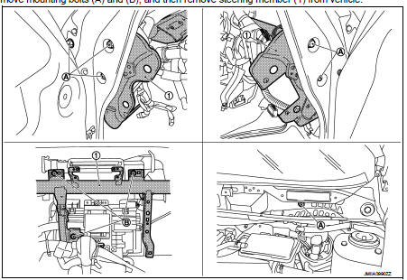
18. Remove mounting bolts (A) and (B), and then remove steering member (1) from
vehicle.
19. Remove A/C unit assembly from vehicle.
INSTALLATION
Note the following items, and then install in the reverse order of removal.
CAUTION:
• Replace O-rings with new ones. Then apply compressor oil to them when
installing.
• Check for leakages when recharging refrigerant. Refer to HA-19, "Leak Test".
NOTE:
Refer to CO-38, "Refilling" when filling radiator with engine coolan
Evaporator : Removal and Installation
REMOVAL
1. Remove A/C unit assembly. Refer to HA-53, "A/C UNIT ASSEMBLY : Removal and Installation".
2. Disassemble A/C unit assembly, and then remove evaporator.
3. Remove intake sensor from evaporator. (automatic air conditioning) 4. Remove thermo control amp. from evaporator. (manual air conditioning) 5. Remove mounting bolts, and then remove expansion valve.
INSTALLATION
Note the following items, and then install in the reverse order of removal.
CAUTION:
• Replace O-rings with new ones. Then apply compressor oil to them when
installing.
• When install the intake sensor (automatic air conditioning) or the thermo control amp. (manual air conditioning), set the same position before replacement.
• Never rotate the bracket insertion part when removing and installing the intake sensor (automatic air conditioning) or the thermo control amp. (manual air conditioning).
• Perform lubricant adjusting procedure after installing new evaporator. Refer to HA-23, "Lubricant Adjusting Procedure for Components Replacement Except Compressor".
HEATER CORE : Removal and Installation
REMOVAL
1. Remove A/C unit assembly. Refer to HA-53, "A/C UNIT ASSEMBLY : Removal and Installation".
2. Remove heater pipe grommet and heater pipe support from A/C unit assembly.
3. Remove foot duct LH. Refer to VTL-14, "FOOT DUCT : Removal and Installation".
4. Remove heater core side packing. (LHD models only) 5. Slide heater core to leftward, and then remove heater core from A/C unit assembly.
INSTALLATION
Install in the reverse order of removal.
Expansion valve : Removal and Installation
CAUTION:
Perform lubricant return operation before each refrigeration system disassembly.
However, if a large
amount of refrigerant or lubricant is detected, never perform lubricant return
operation. Refer to HA-
23, "Perform Lubricant Return Operation".
REMOVAL
1. Use a refrigerant collecting equipment (for HFC-134a) to discharge the refrigerant. Refer to HA-21, "Recycle Refrigerant".
2. Remove plastic nut, and then move lower dash insulator aside.
 : Plastic nut
3. Remove mounting bolt (A), and then disconnect low-pressure flexible hose (1) and high-pressure pipe (2) from expansion valve.
CAUTION:
Cap of wrap the joint of the A/C piping and expansion valve
with suitable material such as vinyl tape to avoid the entry
of air.
4. Remove mounting bolts (A), and then remove expansion valve from evaporator.
INSTALLATION
Note the following items, and then install in the reverse order of removal.
CAUTION:
• Replace O-rings with new ones. Then apply compressor oil to them when
installing.
• Check for leakages when recharging refrigerant. Refer to HA-19, "Leak Test".
 Condenser
Exploded View
1. Condenser
2. Refrigerant pressure sensor
3. O-ring
4. Grommet
5. Braket
6. O-ring
7. Liquid tank braket
8. Liquid tank
: Do not reuse
: N·m (kg-m, in-lb)
: N·m (kg ...
 Service data and specifications (SDS)
Compressor
Lubricant
Refrigerant
Engine Idling Speed
Refer to EC-807, "Idle Speed".
Belt Tension
Refer to EM-154, "Checking". ...
Other materials:
B1210 side collision detection
Description
The side air bag and curtain air bag are activated by the air bag diagnosis
sensor unit signal transmitted at the
time of side collision.
DTC Logic
DTC DETECTION LOGIC
DTC CONFIRMATION PROCEDURE
1.CHECK SELF-DIAG RESULT
With CONSULT-III
1. Turn ignition switch ON.
2. Perform ...
Parking brake control
Exploded View
2WD
1. Parking brake lever assembly
2. Adjusting nut
3. Parking brake switch
4. Front cable
5. Rear cable (LH)
6. Rear cable (RH)
: Apply multi-purpose grease.
: N·m (kg-m, ft-lb)
: N·m (kg-m, in-lb)
: Always replace after every
disassembly.
4WD
1. Parking brak ...
Rear window defogger does not operate but both door
mirror defoggers operate
Diagnosis Procedure
1.CHECK REAR WINDOW DEFOGGER
Check rear window defogger.
Refer to DEF-31, "Component Function Check".
Is the inspection result normal?
YES >> GO TO 2.
NO >> Repair or replace the malfunctioning parts.
2.CONFIRM THE OPERATION
Confirm the opera ...
