Nissan Juke Service and Repair Manual : Condenser
Exploded View
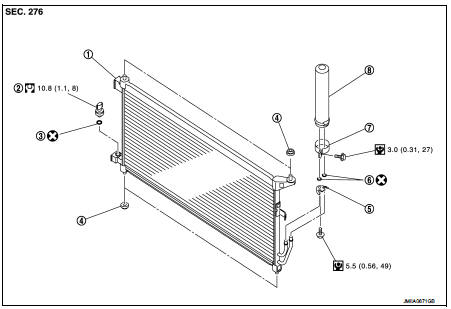
1. Condenser
2. Refrigerant pressure sensor
3. O-ring
4. Grommet
5. Braket
6. O-ring
7. Liquid tank braket
8. Liquid tank
 : Do not reuse
 : N·m (kg-m, in-lb)
 : N·m (kg-m, ft-lb)
Condenser : Removal and Installation
CAUTION:
Perform lubricant return operation before each refrigeration system disassembly.
However, if a large
amount of refrigerant or lubricant is detected, never perform lubricant return
operation. Refer to HA-
23, "Perform Lubricant Return Operation".
REMOVAL
1. Use a refrigerant collecting equipment (for HFC-134a) to discharge the refrigerant. Refer to HA-21, "Recycle Refrigerant".
2. Remove radiator core support upper. Refer to DLK-147, "HR16DE : Removal and Installation".
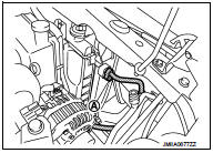
3. Remove mounting bolt (A), and then disconnect high-pressure flexible hose from condenser.
CAUTION:
Cap or wrap the joint of the A/C piping and condenser with
suitable material such as vinyl tape to avoid the entry of air.
Remove mounting bolt (A), and then disconnect high-pressure pipe from condenser.
CAUTION:
Cap or wrap the joint of the A/C piping and condenser with
suitable material such as vinyl tape to avoid the entry of air.
5. Remove condenser from vehicle.
CAUTION:
Be careful not to damage core surface of condenser.
INSTALLATION
Note the following items, and then install in the reverse order of removal.
CAUTION:
• Replace O-rings with new ones. Then apply compressor oil to them when
installing.
• Perform lubricant adjusting procedure before installing new condenser. Refer to HA-24, "Lubricant Adjusting Procedure for Compressor Replacement".
• Check for leakages when recharging refrigerant. Refer to HA-19, "Leak Test".
Liquid tank : Removal and Installation
CAUTION:
Perform lubricant return operation before each refrigeration system disassembly.
However, if a large
amount of refrigerant or lubricant is detected, never perform lubricant return
operation. Refer to HA-
23, "Perform Lubricant Return Operation".
REMOVAL
1. Use a refrigerant collecting equipment (for HFC-134a) to discharge the refrigerant. Refer to HA-21, "Recycle Refrigerant".
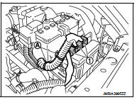
2. Disconnect battery cable from negative terminal. Refer to PG-125, "Removal and Installation".
3. Disconnect harness connectors (1) from battery terminal with fusible link.
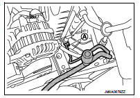
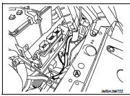
4. Remove harness fixing clips (A) from F/L · fuse holder bracket.
5. Remove harness fixing clips (A) from F/L · fuseholder bracket.
6. Disconnect harness connector (1) from ECM.
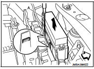
7. Disengage fixing pawls using a remover tool (A), and then remove F/L · fuse holder.
 : Vehicle front
8. Move F/L · fuse holder and harness to a location where they do not inhibit work.
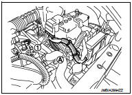
9. Remove harness fixing clip (A) from F/L · fuse holder bracket.
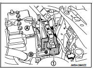
10. Remove mounting bolt (A) and nut (B) of F/L · fuse holder bracket (1), and then remove F/L · fuse holder bracket.
: Vehicle front
11. Clean liquid tank and its surrounding area, and then remove dust and rust from liquid tank.
12. Remove mounting bolts, and then remove liquid tank from the condenser.
CAUTION:
Cap or wrap the joint of the A/C piping and liquid tank with suitable material
such as vinyl tape to
avoid the entry of air.
INSTALLATION
Note the following items, and install in the reverse order of removal.
CAUTION:
• Replace O-rings of the A/C piping with new ones. Then apply compressor oil to
them when installing.
• Perform lubricant adjusting procedure before installing new liquid tank. Refer to HA-24, "Lubricant Adjusting Procedure for Compressor Replacement".
• Check for leakages when recharging refrigerant. Refer to HA-19, "Leak Test".
Refrigerant pressure sensor : Removal and Installation
CAUTION:
Perform lubricant return operation before each refrigeration system disassembly.
However, if a large
amount of refrigerant or lubricant is detected, never perform lubricant return
operation. Refer to HA-
23, "Perform Lubricant Return Operation".
REMOVAL
1. Use a refrigerant collecting equipment (for HFC-134a) to discharge the refrigerant. Refer to HA-21, "Recycle Refrigerant".
2. Clean refrigerant pressure sensor and its surrounding area, and then remove dust and rust from refrigerant pressure sensor.
3. Disconnect refrigerant pressure sensor connector.
4. Use a adjustable wrench or other tool to hold the refrigerant pressure sensor mounting block, and then remove the refrigerant pressure sensor from the condenser.
CAUTION:
• Be careful not to damage core surface of condenser.
• Cap or wrap the joint of the condenser and liquid tank with suitable material such as vinyl tape to avoid the entry of air.
INSTALLATION
Note the following items, and then install in the reverse order of removal.
CAUTION:
• Replace O-ring with new one. Then apply compressor oil to them when
installing.
• Check for leakages when recharging refrigerant. Refer to HA-19, "Leak Test".
 Cooler pipe and hose
Exploded View
1. A/C unit assembly
2. O-ring
3. High-pressure pipe
4. Condenser
5. Low-pressure flexible hose
6. O-ring
7. Compressor
8. O-ring
9. High-pressure flexible hose
: Do no ...
 A/C unit assembly
Exploded View (Automatic Air Conditioning)
REMOVAL
LHD model
1. A/C unit assembly
2. Drain hose
3. Steering member
4. Instrument stay
: Clip
: N·m (kg-m, ft-lb)
DISASSEMBLY
LHD models
...
Other materials:
Injection tube and fuel injector
Exploded View
1. Spill hose
2. Injection tube
3. Fuel injector
4. Heat protection washer
5. Fuel injector bracket
6. Fuel injector bracket spacer
7. Fuel rail stud bolt
8. Fuel rail
9. High pressure protection cover (lower)
10. Injection tube
11. High pressure supply pump
12. H ...
Water hose
Exploded View
1. Hose clamp
2. Water hose A
3. Water hose B
4. Water hose B
5. Water bypass pipe
6. Hose clamp
7. Heater hose
8. Water hose C
A. Water outlet
B. Heater thermostat
C. Oil warmer
D. Heater core
: N·m (kg-m, in-lb)
Removal and Installation
REMOVAL
WARNING:
Nev ...
IGN off interlock door unlock function does not operate
Diagnosis Procedure
1.CHECK “AUTOMATIC LOCK/UNLOCK SELECT” SETTING IN “WORK SUPPORT”
1. Select “DOOR LOCK” of “BCM” using CONSULT-III.
2. Select “AUTOMATIC LOCK/UNLOCK SELECT” in “WORK SUPPORT” mode.
3. Check “AUTOMATIC LOCK/UNLOCK SELECT” in “WORK SUPPORT”.
Re ...
