Nissan Juke Service and Repair Manual : P0651 sensor power supply
DTC Logic
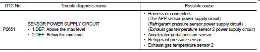
DTC DETECTION LOGIC
Diagnosis Procedure
1.CHECK GROUND CONNECTION
1. Turn ignition switch OFF.
2. Check ground connection E38. Refer to Ground Inspection in GI-44, "Circuit Inspection".
Is the inspection result normal? YES >> GO TO 2.
NO >> Repair or replace ground connection.
2.CHECK SENSOR POWER SUPPLY CIRCUITS
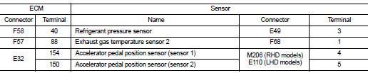
Check harness for short to power and short to ground, between the following terminals.
Is the inspection result normal? YES >> GO TO 3.
NO >> Repair short to ground or short to power in harness or connectors.
3.CHECK INTERMITTENT INCIDENT
Refer to GI-42, "Intermittent Incident", ???INCIDENT SIMULATION TESTS??? and ???GROUND INSPECTION???.
>> INSPECTION END
 P0641 sensor power supply
DTC Logic
DTC DETECTION LOGIC
Diagnosis Procedure
1.CHECK GROUND CONNECTION
1. Turn ignition switch OFF.
2. Check ground connection E38. Refer to Ground Inspection in GI-44, "Circuit
Ins ...
 P0657 ECM relay
DTC Logic
DTC DETECTION LOGIC
NOTE:
When IPDM E/R DTC is indicated with DTC P0657, IPDM E/R DTC must be checked
first.
Diagnosis Procedure
1.CHECK GROUND CONNECTION
1. Turn ignition switch O ...
Other materials:
B1202, B1203, B1204, B1205, B1206, B1207 diagnosis sensor unit
DTC Logic
DTC DETECTION LOGIC
DTC CONFIRMATION PROCEDURE
1.CHECK SELF-DIAG RESULT
With CONSULT-III
1. Turn ignition switch ON.
2. Perform “Self Diagnostic Result” mode of “AIR BAG” using CONSULT-III.
Without CONSULT-III
1. Turn ignition switch ON.
2. Check the air bag warning la ...
Fluid cooler system
Exploded View
1. Bracket
2. Bracket
3. Bracket
4. CVT fluid cooler
5. Clamp
6. CVT fluid cooler hose C
7. CVT fluid cooler hose B
8. CVT fluid cooler tube assembly
9. CVT fluid cooler hose D
10. CVT fluid cooler hose A
11. Transaxle assembly
A. CVT oil warmer
: Vehicle front
: ...
B27B0 A/C auto AMP.
DTC Logic
DTC DETECTION LOGIC
NOTE:
• If DTC is displayed along with DTC U1000, first perform the trouble diagnosis
for DTC U1000. Refer to HAC-
141, "DTC Logic".
• If DTC is displayed along with DTC U1010, first perform the trouble diagnosis
for DTC U1010. HAC-142,
"DTC ...
