Nissan Juke Service and Repair Manual : B1202, B1203, B1204, B1205, B1206, B1207 diagnosis sensor unit
DTC Logic
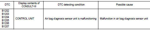
DTC DETECTION LOGIC
DTC CONFIRMATION PROCEDURE
1.CHECK SELF-DIAG RESULT
 With CONSULT-III
1. Turn ignition switch ON.
2. Perform ÔÇťSelf Diagnostic ResultÔÇŁ mode of ÔÇťAIR BAGÔÇŁ using CONSULT-III.
 Without CONSULT-III
1. Turn ignition switch ON.
2. Check the air bag warning lamp status. Refer to SRC-12, "On Board Diagnosis Function".
NOTE
:
SRS does not enter the diagnosis mode if no malfunction is detected in the user
mode.
Is malfunctioning part detected? YES >> Refer to SRC-139, "Diagnosis Procedure".
NO >> INSPECTION END
Diagnosis Procedure
WARNING:
ÔÇó Before servicing, turn ignition switch OFF, disconnect battery negative
terminal, and wait at least 3
minutes or more. (To discharge backup capacitor.)
ÔÇó Never use unspecified tester or other measuring device.
1.CHECK HARNESS CONNECTOR
Check the harness connector.
Is the inspection result normal? YES >> GO TO 2.
NO >> Replace harness connectors.
2.CHECK WIRING HARNESS
Check the wiring harness externals.
Is the inspection result normal? YES >> GO TO 3.
NO >> Replace wiring harness.
3.REPLACE AIR BAG DIAGNOSIS SENSOR UNIT
1. Replace air bag diagnosis sensor unit. Refer to SR-30, "Removal and Installation".
2. Perform DTC confirmation procedure. Refer to SRC-139, "DTC Logic".
Is DTC detected? YES >> GO TO 1.
NO >> INSPECTION END
 B1186, B1187, B1188, B1189, B1190, B1191 diagnosis sensor unit
DTC Logic
DTC DETECTION LOGIC
DTC CONFIRMATION PROCEDURE
1.CHECK SELF-DIAG RESULT
With CONSULT-III
1. Turn ignition switch ON.
2. Perform ÔÇťSelf Diagnostic ResultÔÇŁ mode of ÔÇťAIR BAGÔÇŁ usi ...
 B1209 frontal collision detection
Description
The air bags and seat belt pre-tensioners for driver and passenger are
activated by the air bag diagnosis sensor
unit signal transmitted at the time of the frontal collision.
DTC Logi ...
Other materials:
Changing wheels and tires
Tire rotation
NISSAN recommends rotating the tires every 5,000 miles (8,000 km). (See ÔÇťFlat
tireÔÇŁ for tire replacing procedures.)
As soon as possible, tighten the wheel nuts to the specified torque with a
torque wrench.
Wheel nut tightening torque:
80 ft-lb (108 N┬Ěm)
The wheel ...
Malfunction indicator
Component Function Check
1.CHECK MI FUNCTION
1. Turn ignition switch ON.
2. Make sure that MI lights up.
Is the inspection result normal?
YES >> INSPECTION END
NO >> Go to EC-1019, "Diagnosis Procedure".
Diagnosis Procedure
1.CHECK CAN COMMUNICATION LINE
Refer to LAN ...
U1000 can comm
Description
CAN (Controller Area Network) is a serial communication line for real time
applications. It is an on-vehicle multiplex
communication line with high data communication speed and excellent error
detection ability. Modern
vehicle is equipped with many electronic control unit, and eac ...
