Nissan Juke Service and Repair Manual : B1186, B1187, B1188, B1189, B1190, B1191 diagnosis sensor unit
DTC Logic
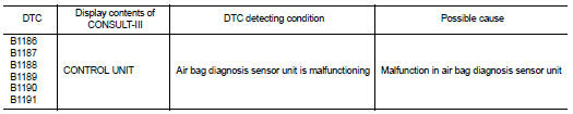
DTC DETECTION LOGIC
DTC CONFIRMATION PROCEDURE
1.CHECK SELF-DIAG RESULT
 With CONSULT-III
1. Turn ignition switch ON.
2. Perform ŌĆ£Self Diagnostic ResultŌĆØ mode of ŌĆ£AIR BAGŌĆØ using CONSULT-III.
 Without CONSULT-III
1. Turn ignition switch ON.
2. Check the air bag warning lamp status. Refer to SRC-12, "On Board Diagnosis Function".
NOTE
:
SRS does not enter the diagnosis mode if no malfunction is detected in the user
mode.
Is malfunctioning part detected? YES >> Refer to SRC-138, "Diagnosis Procedure".
NO >> INSPECTION END
Diagnosis Procedure
WARNING:
ŌĆó Before servicing, turn ignition switch OFF, disconnect battery negative
terminal, and wait at least 3
minutes or more. (To discharge backup capacitor.)
ŌĆó Never use unspecified tester or other measuring device.
1.CHECK HARNESS CONNECTOR
Check the harness connector.
Is the inspection result normal? YES >> GO TO 2.
NO >> Replace harness connectors.
2.CHECK WIRING HARNESS
Check the wiring harness externals.
Is the inspection result normal? YES >> GO TO 3.
NO >> Replace wiring harness.
3.REPLACE AIR BAG DIAGNOSIS SENSOR UNIT
1. Replace air bag diagnosis sensor unit. Refer to SR-30, "Removal and Installation".
2. Perform DTC confirmation procedure. Refer to SRC-138, "DTC Logic".
Is DTC detected? YES >> GO TO 1.
NO >> INSPECTION END
 B1185 lap Pre-tensioner LH
DTC Logic
DTC CONFIRMATION PROCEDURE
1.CHECK SELF-DIAGNOSTIC RESULT
With CONSULT-III
1. Turn ignition switch ON.
2. Perform ŌĆ£Self Diagnostic ResultŌĆØ mode of ŌĆ£AIR BAGŌĆØ using CONSULT-III. ...
 B1202, B1203, B1204, B1205, B1206, B1207 diagnosis sensor unit
DTC Logic
DTC DETECTION LOGIC
DTC CONFIRMATION PROCEDURE
1.CHECK SELF-DIAG RESULT
With CONSULT-III
1. Turn ignition switch ON.
2. Perform ŌĆ£Self Diagnostic ResultŌĆØ mode of ŌĆ£AIR BAGŌĆØ usi ...
Other materials:
Idle air volume learning
Description
Idle Air Volume Learning is a function of ECM to learn the idle air volume
that keeps each engine idle speed
within the specific range. It must be performed under any of the following
conditions:
ŌĆó Each time electric throttle control actuator or ECM is replaced.
ŌĆó Idle speed ...
Cylinder block
Exploded View
1. Cylinder block
2. Top ring
3. Second ring
4. Oil ring
5. Piston
6. Piston pin
7. Snap ring
8. Connecting rod
9. Connecting rod bearing (upper)
10. Connecting rod bearing (lower)
11. Crankshaft key
12. Connecting rod cap
13. Connecting rod cap bolt
14. Main ...
Parking brake switch signal circuit
Diagnosis Procedure
1.CHECK COMBINATION METER INPUT SIGNAL
1. Turn ignition switch ON.
2. Check the voltage between combination meter harness connector and ground.
Is the inspection result normal?
YES >> INSPECTION END
NO >> GO TO 2.
2.CHECK PARKING BRAKE SWITCH SIGNAL CIRCUIT ...
