Nissan Juke Service and Repair Manual : B2601 shift position
DTC Logic
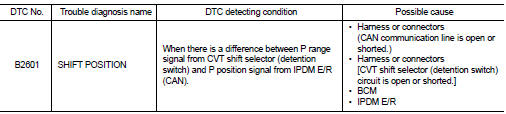
DTC DETECTION LOGIC
NOTE
:
• If DTC B2601 is displayed with DTC U1000, first perform the trouble diagnosis
for DTC U1000. Refer to
BCS-83, "DTC Logic".
• If DTC B2601 is displayed with DTC U1010, first perform the trouble diagnosis for DTC U1010. Refer to BCS-84, "DTC Logic".
DTC CONFIRMATION PROCEDURE
1.PERFORM DTC CONFIRMATION PROCEDURE
1. Shift the selector lever to the P position.
2. Turn ignition switch ON and wait 2 seconds or more.
3. Shift the selector lever to any position other than P, and wait 2 seconds or more.
4. Check DTC in “Self Diagnostic Result” mode of “BCM” using CONSULT-III.
Is DTC detected? YES >> Go to SEC-79, "Diagnosis Procedure".
NO >> INSPECTION END
Diagnosis Procedure
1.CHECK CVT SHIFT SELECTOR POWER SUPPLY
1. Turn ignition switch OFF.
2. Disconnect CVT shift selector (detention switch) connector.
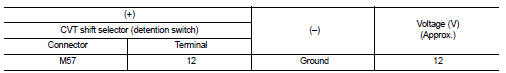
3. Check voltage between CVT shift selector (detention switch) harness connector and ground.
Is the inspection result normal? YES >> GO TO 4.
NO >> GO TO 2.
2.CHECK CVT SHIFT SELECTOR POWER SUPPLY CIRCUIT
1. Disconnect BCM connector.
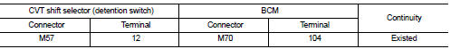
2. Check continuity between CVT shift selector (detention switch) harness connector and BCM harness connector.
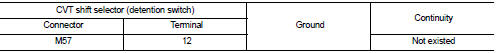
3. Check continuity between CVT shift selector (detention switch) harness connector and ground.
Is the inspection result normal? YES >> GO TO 3.
NO >> Repair or replace harness.
3.REPLACE BCM
1. Replace BCM. Refer to BCS-93, "Removal and Installation".
2. Perform initialization of BCM and registration of all Intelligent Keys using CONSULT-III.
For initialization and registration procedures, refer to CONSULT-III Operation Manual NATS-IVIS/NVIS.
>> INSPECTION END
4.CHECK CVT SHIFT SELECTOR CIRCUIT (IPDM E/R)
1. Disconnect IPDM E/R connector.
2. Check continuity between CVT shift selector (detention switch) harness connector and IPDM E/R harness connector.
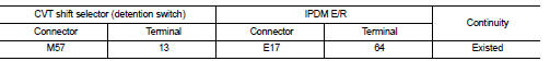
Is the inspection result normal? YES >> GO TO 5.
NO >> Repair or replace harness.
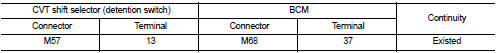
5.CHECK CVT SHIFT SELECTOR CIRCUIT (BCM)
1. Disconnect BCM connector.
2. Check continuity between CVT shift selector (detention switch) harness connector and BCM harness connector.
3. Check continuity between CVT shift selector (detention switch) harness connector and ground.
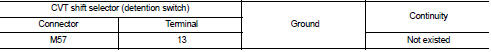
Is the inspection result normal? YES >> GO TO 6.
NO >> Repair or replace harness.
6.REPLACE BCM
1. Replace BCM. Refer to BCS-93, "Removal and Installation".
2. Perform initialization of BCM and registration of all Intelligent Keys using CONSULT-III.
For initialization and registration procedures, refer to CONSULT-III Operation Manual NATS-IVIS/NVIS.
3. Perform DTC CONFIRMATION PROCEDURE for DTC B2601. Refer to SEC-79, "DTC Logic".
Is DTC B2601 detected again? YES >> Replace IPDM E/R. Refer to PCS-34, "Removal and Installation".
NO >> INSPECTION END
 B2557 vehicle speed
DTC Logic
DTC DETECTION LOGIC
NOTE:
• If DTC B2557 is displayed with DTC U1000, first perform the trouble diagnosis
for DTC U1000. Refer to
BCS-83, "DTC Logic".
• If DTC B2557 is ...
 B2602 shift position
DTC Logic
DTC DETECTION LOGIC
NOTE:
• If DTC B2602 is displayed with DTC U1000, first perform the trouble diagnosis
for DTC U1000. Refer to
BCS-83, "DTC Logic".
• If DTC B2602 is ...
Other materials:
Center console assembly
Exploded View
CVT models
1. Console indicator finisher
2. Instrument lower cover RH
3. Center console assembly
4. Instrument lower cover LH
5. Instrument stay
6. CVT shift selector assembly
7. Console rear bracket
8. Console rear finisher
9. Seat heated switch
10. Console switch f ...
Rear wiper motor circuit
Component Function Check
1.CHECK REAR WIPER ON OPERATION
CONSULT-III ACTIVE TEST
1. Select “RR WIPER” of BCM active test item.
2. With operating the test item, check rear wiper operation.
On : Rear wiper ON operation
Off : Stop the rear wiper.
Is rear wiper operation normally?
YES >&g ...
B210D starter relay
DTC Logic
DTC DETECTION LOGIC
NOTE:
If DTC B210D is displayed with DTC U1000, first perform the trouble diagnosis
for DTC U1000. Refer to PCS-
30, "DTC Logic".
DTC CONFIRMATION PROCEDURE
1.PERFORM DTC CONFIRMATION PROCEDURE 1
1. Press push-button ignition switch under the follow ...
