Nissan Juke Service and Repair Manual : B2602 shift position
DTC Logic
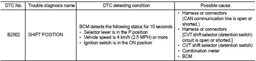
DTC DETECTION LOGIC
NOTE
:
• If DTC B2602 is displayed with DTC U1000, first perform the trouble diagnosis
for DTC U1000. Refer to
BCS-83, "DTC Logic".
• If DTC B2602 is displayed with DTC U1010, first perform the trouble diagnosis for DTC U1010. Refer to BCS-84, "DTC Logic".
DTC CONFIRMATION PROCEDURE
1.PERFORM DTC CONFIRMATION PROCEDURE
1. Start engine.
2. Drive vehicle at a speed of 4 km/h (2.5 MPH) or more for 10 seconds or more.
3. Check DTC in “Self Diagnostic Result” mode of “BCM” using CONSULT-III.
Is DTC detected? YES >> Go to SEC-81, "Diagnosis Procedure".
NO >> INSPECTION END
Diagnosis Procedure
1.CHECK DTC OF “ABS ACTUATOR AND ELECTRIC UNIT (CONTROL UNIT)
”
Check DTC in “Self Diagnostic Result” mode of “ABS” using CONSULT-III.
Is DTC detected? YES >> Perform the trouble diagnosis related to the detected DTC. Refer to BRC-31, "DTC Index" (Without ESP) or BRC-142, "DTC Index" (With ESP).
NO >> GO TO 2.
2.CHECK DTC OF COMBINATION METER
Check DTC in “Self Diagnostic Result” mode of “METER/M&A” using CONSULT-III.
Is DTC detected? YES >> Perform the trouble diagnosis related to the detected DTC. Refer to MWI-36, "DTC Index".
NO >> GO TO 3.
3.CHECK CVT SHIFT SELECTOR POWER SUPPLY
1. Turn ignition switch OFF.
2. Disconnect CVT shift selector (detention switch) connector.
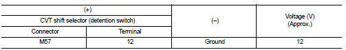
3. Check voltage between CVT shift selector (detention switch) harness connector and ground.
Is the inspection result normal?
YES >> GO TO 6.
NO >> GO TO 4.
4.CHECK CVT SHIFT SELECTOR POWER SUPPLY CIRCUIT
1. Disconnect BCM connector.
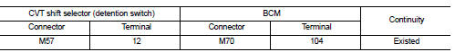
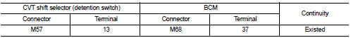
2. Check continuity between CVT shift selector (detention switch) harness connector and BCM harness connector.
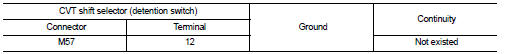
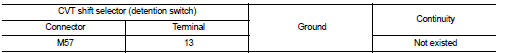
3. Check continuity between CVT shift selector (detention switch) harness connector and ground.
Is the inspection result normal? YES >> GO TO 5.
NO >> Repair or replace harness.
5.REPLACE BCM
1. Replace BCM. Refer to BCS-93, "Removal and Installation".
2. Perform initialization of BCM and registration of all Intelligent Keys using CONSULT-III.
For initialization and registration procedures, refer to CONSULT-III Operation Manual NATS-IVIS/NVIS.
>> INSPECTION END
6.CHECK CVT SHIFT SELECTOR CIRCUIT
1. Disconnect BCM connector and IPDM E/R connector.
2. Check continuity between CVT shift selector (detention switch) harness connector and BCM harness connector.
3. Check continuity between CVT shift selector (detention switch) harness connector and ground.
Is the inspection result normal? YES >> GO TO 7.
NO >> Repair or replace harness.
7.CHECK CVT SHIFT SELECTOR (DETENTION SWITCH)
Refer to SEC-83, "Component Inspection".
Is the inspection result normal? YES >> GO TO 8.
NO >> Replace CVT shift selector. Refer to TM-270, "Removal and Installation" (CVT: RE0F10B) or TM- 481, "Removal and Installation" (CVT: RE0F11A).
8.CHECK INTERMITTENT INCIDENT
Refer to GI-42, "Intermittent Incident".
>> INSPECTION END
Component Inspection
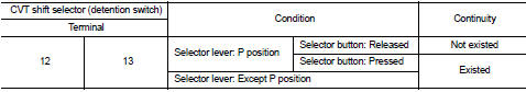
1.CHECK CVT SHIFT SELECTOR (DETENTION SWITCH)
1. Turn ignition switch OFF.
2. Disconnect CVT shift selector connector.
3. Check continuity between CVT shift selector (detention switch) terminals.
Is the inspection result normal? YES >> INSPECTION END
NO >> Replace CVT shift selector. Refer to TM-270, "Removal and Installation" (CVT: RE0F10B) or TM- 481, "Removal and Installation" (CVT: RE0F11A).
 B2601 shift position
DTC Logic
DTC DETECTION LOGIC
NOTE:
• If DTC B2601 is displayed with DTC U1000, first perform the trouble diagnosis
for DTC U1000. Refer to
BCS-83, "DTC Logic".
• If DTC B2601 is ...
 B2603 shift position
DTC Logic
DTC DETECTION LOGIC
NOTE:
• If DTC B2603 is displayed with DTC B2601, first perform the trouble diagnosis
for DTC B2601. Refer to
SEC-79, "DTC Logic".
DTC CONFIRMATION P ...
Other materials:
Rear door lock
Exploded View
1. Outside handle assembly
2. Rear door sealing screen
3. Door lock assembly
4. TORX bolt
5. Inside handle
: Clip
: Pawl
: Vehicle front
: Do not reuse
: N·m (kg-m, in-lb)
: Body grease
Door lock
DOOR LOCK : Removal and Installation
REMOVAL
1. Remove rear door glas ...
Back door does not opened
Diagnosis Procedure
1.CHECK BACK DOOR OPENER SWITCH
Check back door opener switch.
Refer to DLK-384, "Component Function Check".
Is the inspection result normal?
YES >> GO TO 2.
NO >> Repair or replace the malfunctioning parts.
2.CHECK BACK DOOR OPENER ACTUATOR
...
P2120 APP sensor
DTC Logic
DTC DETECTION LOGIC
Diagnosis Procedure
1.CHECK GROUND CONNECTIONS
1. Turn ignition switch OFF.
2. Check ground connection E38. Refer to Ground inspection in GI-44, "Circuit
Inspection".
Is the inspection result normal?
YES >> GO TO 2.
NO >> Repair or ...
