Nissan Juke Service and Repair Manual : B2603 shift position
DTC Logic
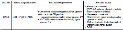
DTC DETECTION LOGIC
NOTE
:
• If DTC B2603 is displayed with DTC B2601, first perform the trouble diagnosis
for DTC B2601. Refer to
SEC-79, "DTC Logic".
DTC CONFIRMATION PROCEDURE
1.PERFORM DTC CONFIRMATION PROCEDURE 1
1. Shift the selector lever to the P position.
2. Turn ignition switch ON and wait 1 second or more.
3. Check DTC in “Self Diagnostic Result” mode of “BCM” using CONSULT-III.
Is DTC detected? YES >> Go to SEC-84, "Diagnosis Procedure".
NO >> GO TO 2.
2.PERFORM DTC CONFIRMATION PROCEDURE 2
1. Shift the selector lever to any position other than P, and wait 1 second or more.
2. Check DTC in “Self Diagnostic Result” mode of “BCM” using CONSULT-III.
Is DTC detected? YES >> Go to SEC-84, "Diagnosis Procedure".
NO >> INSPECTION END
Diagnosis Procedure
1.INSPECTION START
Perform inspection in accordance with procedure that confirms DTC.
Which procedure confirms DTC? DTC confirmation procedure 1>>GO TO 2.
DTC confirmation procedure 2>>GO TO 7.
2.CHECK TRANSMISSION RANGE SWITCH POWER SUPPLY
1. Turn ignition switch OFF.
2. Disconnect transmission range switch connector.
3. Turn ignition switch ON.
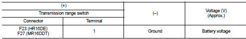
4. Check voltage between transmission range switch harness connector and ground.
Is the inspection result normal?
YES >> GO TO 4.
NO-2 >> GO TO 3.
3.CHECK TRANSMISSION RANGE SWITCH POWER SUPPLY CIRCUIT
1. Turn ignition switch OFF.
2. Disconnect IPDM E/R connector.
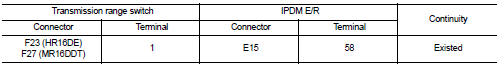
3. Check continuity between transmission range switch harness connector and IPDM E/R harness connector.
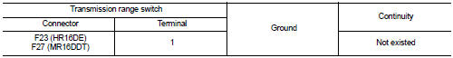
4. Check continuity between transmission range switch harness connector and ground.
Is the inspection result normal? YES >> Check 10 A fuse (No. 56, located in IPDM E/R).
NO >> Repair or replace harness.
4.CHECK BCM INPUT SIGNAL
1. Turn ignition switch OFF.
2. Connect transmission range switch harness connector.
3. Turn ignition switch ON.
4. Check voltage between BCM harness connector and ground.
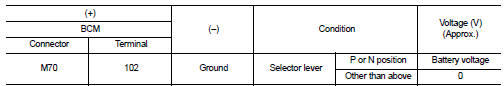
Is the inspection result normal? YES >> GO TO 11.
NO >> GO TO 5.
5.CHECK BCM INPUT SIGNAL CIRCUIT
1. Turn ignition switch OFF.
2. Disconnect transmission range switch connector.
3. Check continuity between transmission range switch harness connector and BCM harness connector.
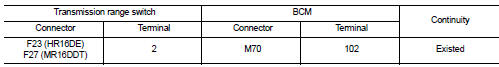
4. Check continuity between transmission range switch harness connector and ground
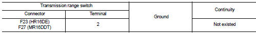
Is the inspection result normal?
YES >> GO TO 6.
NO >> Repair or replace harness.
6.CHECK TRANSMISSION RANGE SWITCH
Refer to SEC-87, "Component Inspection (Transmission Range Switch)".
Is the inspection result normal? YES >> GO TO 12.
NO >> Replace transmission range switch. Refer to TM-278, "Removal and Installation" (CVT: RE0F10B) or TM-508, "Removal and Installation" (CVT: RE0F11A).
7.CHECK CVT SHIFT SELECTOR POWER SUPPLY
1. Turn ignition switch OFF.
2. Disconnect CVT shift selector (detention switch) connector.
3. Check voltage between CVT shift selector (detention switch) harness connector and ground.
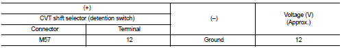
Is the inspection result normal? YES >> GO TO 9.
NO >> GO TO 8.
8.CHECK CVT SHIFT SELECTOR POWER SUPPLY CIRCUIT
1. Disconnect BCM connector.
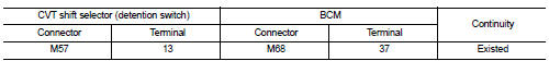
2. Check continuity between CVT shift selector (detention switch) harness connector and BCM harness connector.
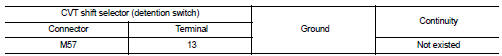
3. Check continuity between CVT shift selector (detention switch) harness connector and ground.
Is the inspection result normal? YES >> GO TO 11.
NO >> Repair or replace harness.
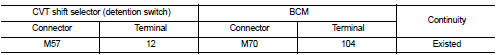
9.CHECK CVT SHIFT SELECTOR CIRCUIT
1. Disconnect BCM connector.
2. Check continuity between CVT shift selector (detention switch) harness connector and BCM harness connector.
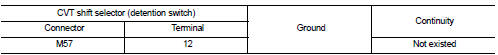
3. Check continuity between CVT shift selector (detention switch) harness connector and ground.
Is the inspection result normal?
YES >> GO TO 10.
NO >> Repair or replace harness.
10.CHECK CVT SHIFT SELECTOR (DETENTION SWITCH)
Refer to SEC-87, "Component Inspection [CVT Shift Selector (Detention Switch)]".
Is the inspection result normal? YES >> GO TO 12.
NO >> Replace CVT shift selector. Refer to TM-270, "Removal and Installation" (CVT: RE0F10B) or TM- 481, "Removal and Installation" (CVT: RE0F11A).
11.REPLACE BCM
1. Replace BCM. Refer to BCS-93, "Removal and Installation".
2. Perform initialization of BCM and registration of all Intelligent Keys using CONSULT-III.
For initialization and registration procedures, refer to CONSULT-III Operation Manual NATS-IVIS/NVIS.
>> INSPECTION END
12.CHECK INTERMITTENT INCIDENT
Refer to GI-42, "Intermittent Incident".
>> INSPECTION END
Component Inspection (Transmission Range Switch)
1.CHECK TRANSMISSION RANGE SWITCH
1. Turn ignition switch OFF.
2. Disconnect transmission range switch connector.
3. Check continuity between transmission range switch terminals.
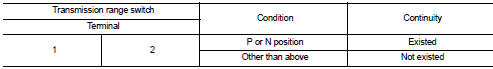
Is the inspection result normal? YES >> INSPECTION END
NO >> Replace transmission range switch. Refer to TM-278, "Removal and Installation" (CVT: RE0F10B) or TM-508, "Removal and Installation" (CVT: RE0F11A).
Component Inspection [CVT Shift Selector (Detention Switch)]
1.CHECK CVT SHIFT SELECTOR (DETENTION SWITCH)
1. Turn ignition switch OFF.
2. Disconnect CVT shift selector connector.
3. Check continuity between CVT shift selector (detention switch) terminals.
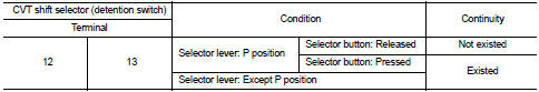
Is the inspection result normal? YES >> INSPECTION END
NO >> Replace CVT shift selector. Refer to TM-270, "Removal and Installation" (CVT: RE0F10B) or TM- 481, "Removal and Installation" (CVT: RE0F11A).
 B2602 shift position
DTC Logic
DTC DETECTION LOGIC
NOTE:
• If DTC B2602 is displayed with DTC U1000, first perform the trouble diagnosis
for DTC U1000. Refer to
BCS-83, "DTC Logic".
• If DTC B2602 is ...
 B2604 shift position
DTC Logic
DTC DETECTION LOGIC
NOTE:
• If DTC B2604 is displayed with DTC U1000, first perform the trouble diagnosis
for DTC U1000. Refer to
BCS-83, "DTC Logic".
• If DTC B2604 is ...
Other materials:
Precaution
Precaution for Supplemental Restraint System (SRS) "AIR BAG" and "SEAT BELT
PRE-TENSIONER"
The Supplemental Restraint System such as “AIR BAG” and “SEAT BELT PRE-TENSIONER”,
used along
with a front seat belt, helps to reduce the risk or severity of injury to the
dr ...
Component parts
Component Parts Location
1. A/C auto amp
Refer to HAC-12, "Component Parts
Location"
2. ECM
Refer to EC-25, "ENGINE CONTROL
SYSTEM :
Component Parts Location"
3. TCM
Refer to TM-314, "CVT CONTROL
SYSTEM : Component Parts Location"
4. EPS control unit
Refer ...
Front drive shaft boot
Exploded View
LEFT SIDE
1. Circular clip
2. Dust shield
3. Housing assembly
4. Boot band
5. Boot
6. Damper band
7. Dynamic damper
8. Circular clip
9. Joint sub-assembly
: Wheel side
: Fill NISSAN Genuine grease or
equivalent.
: Always replace after every
disassembly.
RIGHT ...
