Nissan Juke Service and Repair Manual : Rear oil seal
REAR OIL SEAL : Removal and Installation
REMOVAL
1. Remove transaxle assembly. Refer to TM-301, "Exploded View" (CVT models) or TM-84, "MR16DDT : Exploded View" (M/T models).
2. Remove clutch cover and clutch disk (M/T models). Refer to CL-29, "EXCEPT FOR K9K : Exploded View".
3. Remove drive plate (CVT models) or flywheel (M/T models). Refer to EM-103, "Exploded View".
4. Remove rear oil seal with a suitable tool.
CAUTION:
Be careful not to damage crankshaft and cylinder block.
INSTALLATION
1. Apply the liquid gasket lightly to entire outside area of new rear oil seal.
Use Genuine Liquid Gasket or equivalent.
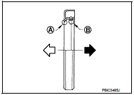
2. Install rear oil seal so that each seal lip is oriented as shown in the figure.
A : Dust seal lip
B : Oil seal lip
 : Engine outside
 : Engine inside
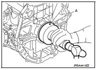
• Press-fit rear oil seal with a suitable drift (A) outer diameter 115 mm (4.53 in) and inner diameter 90 mm (3.54 in).
CAUTION:
• Be careful not to damage crankshaft and cylinder block.
• Press-fit oil seal straight to avoid causing burrs or tilting.
• Never touch grease applied onto oil seal lip.
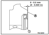
• Press in rear oil seal (1) to the position as shown in the figure.
A : Rear end surface of cylinder block
3. Install in the reverse order of removal, for the rest of parts.
 Front oil seal
FRONT OIL SEAL : Removal and Installation
REMOVAL
1. Remove the following parts.
• Front fender protector (RH): Refer to EXT-22, "Exploded View".
• Drive belt: Refer to EM-20, " ...
 Cylinder head
Exploded View
REMOVAL
1. Cylinder head assembly
2. Cylinder head bolt
3. Cylinder head gasket
A. Tightening must be done following
the installation procedure.
Refer to EM-91
: N·m (kg-m ...
Other materials:
Fuel tank
Exploded View
1. Fuel tank cap
2. Grommet
3. Fuel filler tube
4. Clamp
5. Fuel filler hose
6. Clamp
7. Vent hose
8. Fuel tank
9. Mounting band (RH)
10. Mounting band (LH)
: N·m (kg-m, ft-lb)
Removal and Installation
WARNING:
Be sure to read “General Precautions” when worki ...
The braking distance is long
Description
Brake stopping distance is long when ABS function is operated.
Diagnosis Procedure
CAUTION:
Brake stopping distance on slippery road like rough road, gravel road or snowy
road may become
longer when ABS is operated than when ABS is not operated.
1.CHECK BRAKING FORCE
Check bra ...
Secondary speed sensor
Exploded View
1. Transaxle assembly
2. Secondary speed sensor
3. O-ring
: Always replace after every
disassembly.
: N·m (kg-m, in-lb)
: Genuine NISSAN CVT Fluid NS-2
Removal and Installation
REMOVAL
1. Remove air cleaner case. Refer to EM-26, "Removal and Installation".
2. ...
