Nissan Juke Service and Repair Manual : Blower motor
Exploded View
2WD models
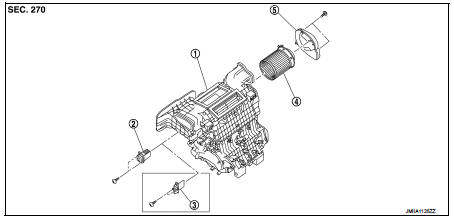
1. A/C unit assembly
2. Fan control amp.*1
3. Blower fan resistor*2
4. Blower motor
5. Blower motor cover
• *1: Automatic air conditioner • *2: Manual air conditioner or Manual heater
4WD models
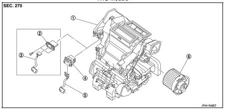
1. A/C unit assembly
2. Blower fan resistor*1
3. Sub harness*1
4. Power transistor*2
5. Sub harness*2
6. Blower motor
• *1: Manual air conditioner • *2: Automatic air conditioner
Removal and Installation (LHD models)
WARNING:
• Before servicing, turn ignition switch OFF, disconnect battery negative
terminal and wait 3 minutes
or more.
• Always work from the side of air bag module. Never work in front of it.
• Never use the air tools or the electric tools for servicing.
REMOVAL
1. Remove glove box assembly. Refer to IP-13, "Removal and Installation".
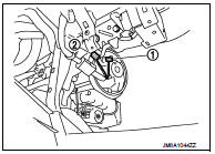
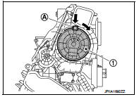
2. Disconnect blower motor harness connector (1) and front passenger air bag module harness connector (2).
3. Remove fixing screws, and then remove blower motor cover. (2WD models
only)
4. Remove front passenger air bag module. Refer to SR-19, "Removal and
Installation".
5. Press flange holding hook (A), and then turn blower motor (1) clockwise.
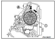
6. Pull outside, and then remove blower motor.
INSTALLATION
Note the following items, and then install in the reverse order of removal.
CAUTION:
• Never use the old mounting bolts after removal, replace with the new bolts.
• Never damage the harness while installing.
• If malfunction is detected by the air bag warning lamp, after repair or replacement of the malfunctioningparts, reset the memory using self-diagnosis or CONSULT-III. Refer to SRC-12, "On Board Diagnosis Function" or SRC-16, "CONSULT-III Function".
• After the work is completed, check that no system malfunction is detected by air bag warning lamp.
Removal and Installation (RHD models)
REMOVAL
1. Remove instrument lower panel. Refer to IP-13, "Removal and Installation".
2. Remove steering column upper cover and steering column lower cover. Refer to IP-13, "Removal and Installation".
3. Remove mounting nuts and harness connector from steering column assembly. Refer to ST-10, "Removal and Installation".
4. Move steering column assembly aside.
5. Disconnect blower motor connector.
6. Press flange holding hook (A), and then turn blower motor (1) clockwise.
7. Pull outside, and then remove blower motor.
INSTALLATION
Install in the reverse order of removal.
 Duct and grille
Exploded View
FRONT
LHD models
1. A/C unit assembly
2. Side ventilator duct LH
3. Foot duct LH
4. Side defroster nozzle LH
5. Side ventilator grille LH
6. Side defroster grille LH
7. In ...
 Air conditioner filter
Exploded View
LHD models
1. A/C unit assembly
2. Air conditioner filter
3. Filter cover
Removal and Installation (LHD models)
REMOVAL
1. Remove glove box assembly. Refer to IP-13, "Rem ...
Other materials:
P0335 CKP sensor (POS)
DTC Logic
DTC DETECTION LOGIC
Diagnosis Procedure
1.CHECK GROUND CONNECTIONS
1. Turn ignition switch OFF.
2. Check ground connection E38. Refer to Ground inspection in GI-44, "Circuit
Inspection".
Is the inspection result normal?
YES >> GO TO 2.
NO >> Repair or ...
Back door does not opened
Diagnosis Procedure
1.CHECK BACK DOOR OPENER SWITCH
Check back door opener switch.
Refer to DLK-513, "Component Function Check".
Is the inspection result normal?
YES >> GO TO 2.
NO >> Repair or replace the malfunctioning parts.
2.CHECK BACK DOOR OPENER ACTUATOR
...
Inside mirror
Exploded View
Manual anti-dazzling type
1. Windshield glass
2. Mirror base
3. Inside mirror assembly
: Do not reuse
Auto anti-dazzling type
1. Rain sensor bracket
2. Mirror base
3. Rain sensor
4. Inside mirror assembly
: Pawl
: Do not reuse
Removal and Installation
CAUTION:
Ne ...
