Nissan Juke Service and Repair Manual : B2627 outside antenna
DTC Logic
DTC DETECTION LOGIC
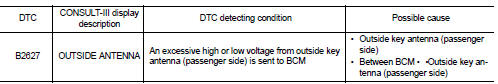
DTC CONFIRMATION PROCEDURE
1.PERFORM DTC CONFIRMATION PROCEDURE
1. Disconnect outside key antenna (passenger side) connector.
2. Perform ÔÇťINTELLIGENT KEYÔÇŁ Self Diagnostic Result.
Is outside key antenna DTC detected? YES >> Refer to DLK-238, "Diagnosis Procedure".
NO >> Outside key antenna (passenger side) is OK.
Diagnosis Procedure
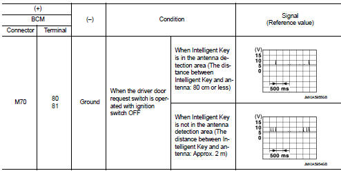
1.CHECK OUTSIDE KEY ANTENNA INPUT SIGNAL 1
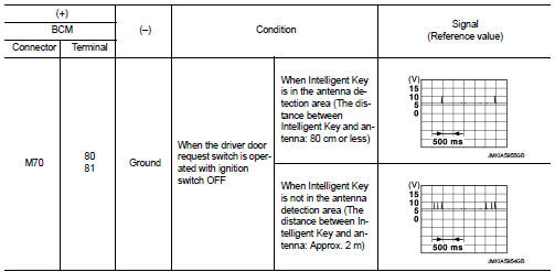
1. Turn ignition switch OFF.
2. Check signal between BCM harness connector and ground using oscilloscope.
Is the inspection result normal? YES >> Replace BCM. Refer to BCS-93, "Removal and Installation".
NO >> GO TO 2.
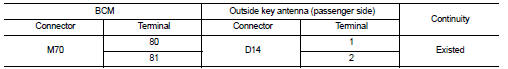
2.CHECK OUTSIDE KEY ANTENNA CIRCUIT
1. Disconnect BCM connector and outside key antenna (passenger side) connector.
2. Check continuity between BCM harness connector and outside key antenna (passenger side) harness connector.
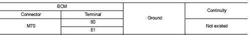
3. Check continuity between BCM harness connector and ground.
Is the inspection result normal? YES >> GO TO 3.
NO >> Repair or replace harness.
3.CHECK OUTSIDE KEY ANTENNA INPUT SIGNAL 2
1. Replace outside key antenna (passenger side). (New antenna or other
antenna)
2. Connect BCM connector and outside key antenna (passenger side) connector.
3. Check signal between BCM harness connector and ground using oscilloscope.
Is the inspection result normal? YES >> Replace outside key antenna (passenger side).
NO >> Replace BCM. Refer to BCS-93, "Removal and Installation".
 B2626 OUTSIDE ANTENNA
DTC Logic
DTC DETECTION LOGIC
DTC CONFIRMATION PROCEDURE
1.PERFORM DTC CONFIRMATION PROCEDURE
1. Disconnect outside key antenna (driver side) connector.
2. Perform ÔÇťINTELLIGENT KEYÔÇŁ Self Di ...
 B2628 outside antenna
DTC Logic
DTC DETECTION LOGIC
DTC CONFIRMATION PROCEDURE
1.PERFORM DTC CONFIRMATION PROCEDURE
1. Disconnect outside key antenna (rear bumper) connector.
2. Perform ÔÇťINTELLIGENT KEYÔÇŁ Self Di ...
Other materials:
Hazard switch
Component Function Check
1.CHECK HAZARD SWITCH SIGNAL BY CONSULT-III
CONSULT-III DATA MONITOR
1. Turn the ignition switch ON.
2. Select ÔÇťHAZARD SWÔÇŁ of BCM (FLASHER) data monitor item.
3. With operating the hazard switch, check the monitor status.
Is the inspection result normal?
YES > ...
P0743 torque converter
DTC Logic
DTC DETECTION LOGIC
DTC CONFIRMATION PROCEDURE
CAUTION:
Be careful of the driving speed.
1.PREPARATION BEFORE OPERATION (PART 1)
If another "DTC CONFIRMATION PROCEDURE" occurs just before, turn ignition
switch OFF and wait for at
least 10 seconds, then perform the next ...
Ignition timing
Description
This describes how to check the ignition timing. For the actual procedure,
follow the instructions in ÔÇťBASIC
INSPECTIONÔÇŁ.
Special Repair Requirement
1.CHECK IGNITION TIMING
1. Attach timing light to the ignition coil No.4 harness.
2. Check ignition timing.
1 : Timing indicat ...
