Nissan Juke Service and Repair Manual : Air conditioner filter
Exploded View
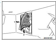
LHD models
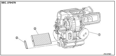
1. A/C unit assembly 2. Air conditioner filter 3. Filter cover
Removal and Installation (LHD models)
REMOVAL
1. Remove glove box assembly. Refer to IP-13, "Removal and Installation".
2. Remove filter cover (1), and then remove air conditioner filter (2) from A/C unit assembly.
CAUTION:
If the filter is deformed/damaged when removing, replace it
with a new one. Deformed/damaged filter may deteriorate
the dust collecting performance.
INSTALLATION
Note the following item, and install in the reverse order of removal.
CAUTION:
When installing, handle the filter with extreme care to avoid
deforming/damaging.
Removal and Installation (RHD models)
REMOVAL
NOTE
:
When removing air conditioner filter, visually check the operation through glove
box mask opening.
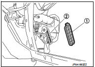
1. Open glove box lid. Remove glove box mask.
 : Pawl
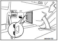
2. Remove filter cover according to the numerical order as shown in the figure, while putting a hand through bottom of glove box and pressing pawl (A) of filter cover.
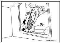
3. Pull out air conditioner filter from A/C unit assembly according to the numerical order as shown in the figure. Remove air conditioner filter through bottom of glove box.
CAUTION:
If the filter is deformed/damaged when removing, replace it with a new one.
Deformed/damaged filter
may deteriorate the dust collecting performance.
INSTALLATION
NOTE
:
When removing air conditioner filter, visually check the operation through glove
box mask opening.
CAUTION:
When installing, handle the filter with extreme care to avoid
deforming/damaging.
Replacement
Replace Air conditioner filter.
Refer to VTL-20, "Air Conditioner Filter".
 Blower motor
Exploded View
2WD models
1. A/C unit assembly
2. Fan control amp.*1
3. Blower fan resistor*2
4. Blower motor
5. Blower motor cover
• *1: Automatic air conditioner
• *2: Manual air con ...
 Service data and specifications (SDS)
Air Conditioner Filter
...
Other materials:
Additional service when replacing control unit
ECM
ECM : Description
Performing the following procedure can automatically activate recommunication
of ECM and BCM, but only
when the ECM is replaced with a new one*.
*: New one means a virgin ECM that has never been energized on-board.
(In this step, initialization procedure by CONSULT-I ...
P0715 input speed sensor A
DTC Logic
DTC DETECTION LOGIC
DTC CONFIRMATION PROCEDURE
CAUTION:
Be careful of the driving speed.
1.PREPARATION BEFORE WORK
If another "DTC CONFIRMATION PROCEDURE" occurs just before, turn ignition
switch OFF and wait for at
least 10 seconds, then perform the next test.
> ...
B terminal circuit
Description
“B” terminal circuit supplies power to charge the battery and to operate the
vehicle’s electrical system.
Diagnosis Procedure
1.CHECK “B” TERMINAL CONNECTION
1. Turn ignition switch OFF.
2. Check if “B” terminal is clean and tight.
Is the inspection result normal? ...
