Nissan Juke Service and Repair Manual : Flushing
1. Install reservoir tank if removed and radiator drain plug.
CAUTION:
Be sure to clean drain plug and install with new O-ring.
Radiator drain plug : Refer to CO-42, "Exploded View".
• If water drain plugs on cylinder block are removed, close and tighten them. Refer to EM-228, "Disassembly and Assembly".
2. EM-161, "Exploded View"Remove air duct (between air cleaner case and electric throttle control actuator).
Refer to .
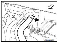
3. Disconnect heater hose (1) at position (
) in the figure.
 : Vehicle front
• Enhance heater as high as possible.
4. Fill radiator and reservoir tank with water and reinstall radiator cap.
• When engine coolant over flows disconnected heater hose, connect heater hose, and continue filling the engine coolant.
5. Install air duct (between air cleaner case and electric throttle control actuator). Refer to EM-161, "Exploded View".
6. Run the engine and warm it up to normal operating temperature.
7. Rev the engine two or three times under no-load.
8. Stop the engine and wait until it cools down.
9. Drain water from the system. Refer to CO-37, "Draining".
10. Repeat steps 1 through 9 until clear water begins to drain from radiator.
 Refilling
1. Install reservoir tank if removed and radiator drain plug.
CAUTION:
Be sure to clean drain plug and install with new O-ring.
Radiator drain plug : Refer to CO-42, "Exploded View".
â ...
 Radiator
...
Other materials:
Vehicle jerks during
Description
The vehicle jerks when ABS function and EBD function operates.
Diagnosis Procedure
1.CHECK SYMPTOM
Check that the vehicle jerks when ABS function and EBD function operates.
Is the inspection result normal?
YES >> Normal
NO >> GO TO 2.
2.PERFORM SELF-DIAGNOSIS
Wit ...
Service Notice or Precautions for Transfer
• After overhaul refill the transfer with new transfer oil.
• Check the oil level or replace the oil only with the vehicle parked on level
surface.
• During removal or installation, keep inside of transfer clear of dust or
dirt.
• Replace all tires at the same time. Always use tires o ...
Instrument Panel
Air ventilation vents
Meters and gauges cluster:
Vehicle information display
Center multi-function control panel*
Hazard warning flasher switch
Rear window and outside mirror defroster switch (if so equipped)
F ...
