Nissan Juke Service and Repair Manual : Diagnosis system (ipdm e/r) (with intelligent key system)
Diagnosis Description
AUTO ACTIVE TEST
Description
In auto active test mode, the IPDM E/R sends a drive signal to the following
systems to check their operation.
ŌĆó Oil pressure warning lamp (only for K9K engine models)
ŌĆó Rear window defogger
ŌĆó Front wiper motor
ŌĆó Parking lamp
ŌĆó License plate lamp
ŌĆó Tail lamp
ŌĆó Front fog lamp
ŌĆó Headlamp (LO, HI)
ŌĆó A/C compressor (magnet clutch)
ŌĆó Cooling fan
Operation Procedure
CAUTION:
Wiper arm interferes with food when wiper is operated while wiper arm is in the
raised position.
Always perform auto active test without setting wiper arm in the raised position. Always pour water on front windshield glass in advance to auto active test so that damage on front windshield glass surface is prevented.
1. Turn the ignition switch OFF.
2. Turn the ignition switch ON, and within 20 seconds, press the driver door switch 10 times. Then turn the ignition switch OFF.
CAUTION:
Close passenger door.
3. Turn the ignition switch ON within 10 seconds. After that the horn sounds once and the auto active test starts.
CAUTION:
Engine starts when ignition switch is turned ON while brake pedal is depressed.
4. Oil pressure warning lamp starts blinking when the auto active test starts*. (only for K9K engine models)
*: Except for K9K engine models, oil pressure warning lamp turn ON when auto active test start.
5. After a series of the following operations is repeated 3 times, auto active test is completed.
NOTE
:
ŌĆó When auto active test mode has to be cancelled halfway through test, turn the
ignition switch OFF.
ŌĆó When auto active test is not activated, door switch may be the cause. Check door switch. Refer to DLK-87, "Component Function Check" (with super lock) or DLK-258, "Component Function Check" (without super lock).
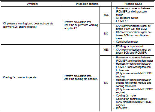
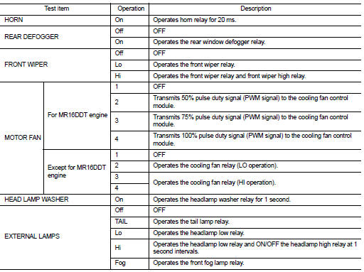
Inspection in Auto Active Test Mode When auto active test mode is actuated, the following operation sequence is repeated 3 times.
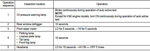
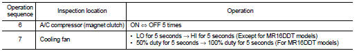
Concept of auto active test
*: Only for models with MR16DDT engine
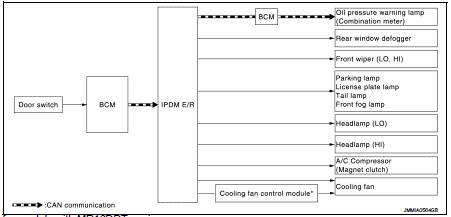
ŌĆó IPDM E/R starts the auto active test with the door switch signals transmitted by BCM via CAN communication.
Therefore, the CAN communication line between IPDM E/R and BCM is considered normal if the auto active test starts successfully.
ŌĆó The auto active test facilitates troubleshooting if any systems controlled by IPDM E/R cannot be operated.
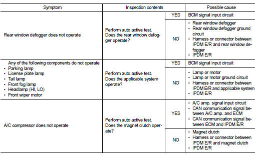
Diagnosis chart in auto active test mode
Consult-III Function (IPDM E/R)
APPLICATION ITEM
CONSULT-III performs the following functions via CAN communication with IPDM E/R.
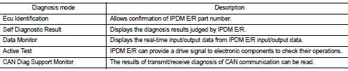
SELF DIAGNOSTIC RESULT
Refer to PCS-25, "DTC Index".
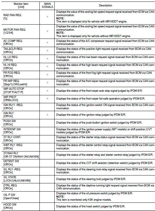
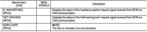
DATA MONITOR
Monitor item
ACTIVE TEST
Test item
 Diagnosis system (BCM) (without intelligent key system)
Common item
COMMON ITEM : CONSULT-III Function (BCM - COMMON ITEM)
APPLICATION ITEM
CONSULT-III performs the following functions via CAN communication with BCM.
SYSTEM APPLICATION
BCM can perfo ...
 Diagnosis system (IPDM E/R) (without intelligent key system)
Diagnosis Description
AUTO ACTIVE TEST
Description
In auto active test mode, the IPDM E/R sends a drive signal to the following
systems to check their operation.
ŌĆó Oil pressure warning lamp ...
Other materials:
Doors
WARNING
ŌĆó Always have the doors locked while driving. Along with the use of
seat belts, this provides greater safety in the event of an accident by helping
to prevent persons from being thrown from the vehicle. This also helps keep children
and others from unintentionally opening the ...
Avoiding collision and rollover
WARNING
Failure to operate this vehicle in a safe, alert, and prudent manner significantly increases the risk of a dangerous situation and may result in an immediate loss of control or a severe accident.
Be alert, anticipate potential hazards, and drive defensively at all times behind the ...
Radiator cap : Inspection
ŌĆó Check valve seat (A) of radiator cap.
B : Metal plunger
- Check that valve seat is swollen to the extent that the edge of the
plunger cannot be seen when watching it vertically from the top.
- Check that valve seat has no soil and damage.
ŌĆó Pull negative-pressure valve to open it, and t ...
