Nissan Juke Service and Repair Manual : S terminal circuit
Description
The starter motor magnetic switch is supplied with power when the ignition switch is turned to the START position while the selector lever is in the P or N position for CVT models or the clutch pedal is depressed for M/T models.
Diagnosis Procedure
CAUTION:
Perform diagnosis under the condition that engine cannot start by the following
procedure.
1. Remove fuel pump fuse.
2. Crank or start the engine (where possible) until the fuel pressure is released.
1.CHECK “S” TERMINAL CIRCUIT
1. Turn ignition switch OFF.
2. Disconnect starter motor connector.
3. Shift selector lever to “P” or “N” position. (CVT models) Keep depressing clutch pedal fully. (M/T models) 4. Check voltage between starter motor harness connector and ground.
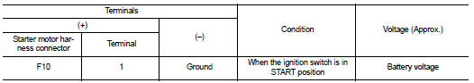
Is the inspection result normal? YES >> “S” terminal circuit is OK. Further inspection is necessary. Refer to STR-14, "Work Flow".
NO >> GO TO 2.
2.CHECK HARNESS CONTINUITY (OPEN CIRCUIT)
1. Disconnect IPDM E/R connector.
2. Check continuity between starter motor harness connector and IPDM E/R harness connector.
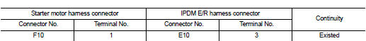
Is the inspection result normal? YES >> Further inspection is necessary. Refer to STR-14, "Work Flow".
NO >> Repair the harness.
 B terminal circuit
Description
The “B” terminal is constantly supplied with battery power.
Diagnosis Procedure
CAUTION:
Perform diagnosis under the condition that engine cannot start by the following
procedure ...
 Symptom diagnosis
STARTING SYSTEM
Symptom Table
...
Other materials:
Vehicle security system cannot BE set
INTELLIGENT KEY
INTELLIGENT KEY : Description
Armed phase is not activated when door is locked using Intelligent Key.
NOTE:
Check that vehicle is under the condition shown in “CONDITIONS OF VEHICLE
(OPERATING CONDITIONS)”
before starting diagnosis, and check each symptom.
CONDITION O ...
Brake booster
Exploded View
2WD
MR16DDT, HR16DE
1. Master cylinder assembly
2. Vacuum pipe
3. Brake booster
4. Lock nut
5. Clevis
6. Gasket
: N·m (kg-m, ft-lb)
K9K
1. Master cylinder assembly
2. Vacuum pipe
3. Brake booster
4. Lock nut
5. Clevis
6. Gasket
: N·m (kg-m, ft-lb)
4WD
...
Component parts
Component Parts Location
1. Remote keyless entry receiver
Refer to DLK-21,
"Component Parts Location" (With
super lock) or DLK-198,
"Component Parts Location" (Without
super lock).
2. Combination meter
Refer to MWI-4, "METER SYSTEM :
Component Parts Location" ...
