
Nissan Juke Service and Repair Manual : Removal and installation
IPDM E/R
Exploded View
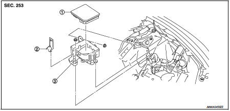
1. IPDM E/R cover A
2. IPDM E/R
3. IPDM E/R cover B
Removal and Installation
CAUTION:
IPDM E/R integrated relays are not serviceable parts, and must not be removed
from the unit.
REMOVAL
1. Remove battery.
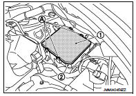
2. Press and expand pawls (A) on lateral side of IPDM E/R cover and remove IPDM E/R (1) from IPDM E/R cover B (2).
3. Disconnect the harness connector and then remove the IPDM E/R.
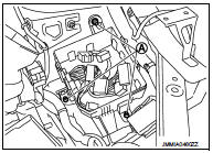
4. Remove IPDM E/R cover B mounting nuts (A).
5. Insert a flat-bladed screwdriver between IPDM E/R cover A (1) and IPDM E/R cover B (2), disengage pawls, and remove IPDM E/R cover A.
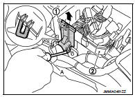
6. Remove IPDM E/R cover B.
INSTALLATION
Install in the reverse order of removal.
 Power supply and ground circuit
Diagnosis Procedure
1.CHECK FUSES AND FUSIBLE LINK
Check that the following IPDM E/R fuses or fusible links are not blown.
Is the fuse fusing?
YES >> Replace the blown fuse or fusible link ...

Other materials:
CVT shift selector
Exploded View
1. Selector lever knob
2. Lock pin
3. Knob cover
4 Position indication panel
5. CVT shift selector assembly
6. CVT shift lock unit
7. Key interlock rod*
8. Indicator lamp
:N·m (kg-m, it-lb)
*: Without push engine starter
Removal and Installation
REMOVAL
CAUTION:
A ...
Wiring diagram
HORN
Wiring Diagram
For connector terminal arrangements, harness layouts, and alphabets in a
(option abbreviation; if not
described in wiring diagram), refer to GI-12, "Connector Information/Explanation
of Option Abbreviation".
...
B2581, B2582 intake sensor
DTC Logic
DTC DETECTION LOGIC
NOTE:
• If DTC is displayed along with DTC U1000, first perform the trouble diagnosis
for DTC U1000. Refer to HAC-
141, "DTC Logic".
• If DTC is displayed along with DTC U1010, first perform the trouble diagnosis
for DTC U1010. HAC-142,
"DTC ...
