Nissan Juke Service and Repair Manual : Power supply and ground circuit
Diagnosis Procedure
1.CHECK FUSES AND FUSIBLE LINK
Check that the following IPDM E/R fuses or fusible links are not blown.

Is the fuse fusing? YES >> Replace the blown fuse or fusible link after repairing the affected circuit if a fuse or fusible link is blown.
NO >> GO TO 2.
2.CHECK POWER SUPPLY CIRCUIT
1. Turn the ignition switch OFF.
2. Disconnect IPDM E/R connector.
3. Check voltage between IPDM E/R harness connector and the ground.
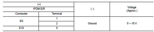
Is the measurement value normal? YES >> GO TO 3.
NO >> Repair the harness or connector.
3.CHECK GROUND CIRCUIT
Check continuity between IPDM E/R harness connectors and the ground.

Does continuity exist? YES >> INSPECTION END
NO >> Repair the harness or connector.
 B2099 ignition relay off stuck
Description
• IPDM E/R operates the ignition relay when it receives an ignition switch ON
signal from BCM via CAN communication.
• Turn the ignition relay OFF by pressing the push-button ignit ...
 Removal and installation
IPDM E/R
Exploded View
1. IPDM E/R cover A
2. IPDM E/R
3. IPDM E/R cover B
Removal and Installation
CAUTION:
IPDM E/R integrated relays are not serviceable parts, and must not be removed
...
Other materials:
Hazard switch
Component Function Check
1.CHECK HAZARD SWITCH SIGNAL BY CONSULT-III
CONSULT-III DATA MONITOR
1. Turn the ignition switch ON.
2. Select “HAZARD SW” of BCM (FLASHER) data monitor item.
3. With operating the hazard switch, check the monitor status.
Is the inspection result normal?
YES > ...
Vehicle security alarm does not activate
Description
Alarm does not operate when alarm operating condition is satisfied.
NOTE:
Check that vehicle is under the condition shown in “CONDITIONS OF VEHICLE
(OPERATING CONDITIONS)”
before starting diagnosis, and check each symptom.
CONDITION OF VEHICLE (OPERATING CONDITIONS)
“SE ...
Windows
Power windows
WARNING
Ensure that all passengers have their hands, fingers, and other belongings safely inside the vehicle while it is in motion and before operating the controls to close the windows. It is highly recommended to use the integrated window lock switch to prevent an ...
