Nissan Juke Service and Repair Manual : Starting system (with intelligent key)
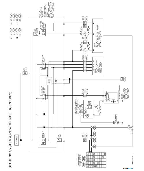
CVT : Wiring Diagram
For connector terminal arrangements, harness layouts, and alphabets in a
 (option abbreviation; if not
described in wiring diagram), refer to GI-12, "Connector Information/Explanation
of Option Abbreviation".
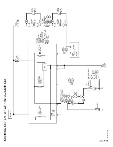
M/T : Wiring Diagram
For connector terminal arrangements, harness layouts, and alphabets in a
 (option abbreviation; if not
described in wiring diagram), refer to GI-12, "Connector Information/Explanation
of Option Abbreviation".
 Wiring diagram
...
 Starting system (without intelligent key)
CVT : Wiring Diagram
For connector terminal arrangements, harness layouts, and alphabets in a
(option abbreviation; if not
described in wiring diagram), refer to GI-12, "Connector Information/ ...
Other materials:
B1184 lap Pre-tensioner LH
DTC Logic
DTC CONFIRMATION PROCEDURE
1.CHECK SELF-DIAGNOSTIC RESULT
With CONSULT-III
1. Turn ignition switch ON.
2. Perform ŌĆ£Self Diagnostic ResultŌĆØ mode of ŌĆ£AIR BAGŌĆØ using CONSULT-III.
Without CONSULT-III
1. Turn ignition switch ON.
2. Check the air bag warning lamp status. Refe ...
Diagnosis system (audio unit)
Models with usb connection function
MODELS WITH USB CONNECTION FUNCTION : On Board Diagnosis Function
Self-diagnosis mode can check the following items.
METHOD OF STARTING
1. Start the engine.
2. Turn OFF audio.
3. While pressing the ŌĆ£SET UPŌĆØ switch, turn the MENU dial counterclockwise
...
P0840 transmission fluid pressure SEN/SW A
DTC Logic
DTC DETECTION LOGIC
DTC CONFIRMATION PROCEDURE
NOTE:
If ŌĆ£DTC CONFIRMATION PROCEDUREŌĆØ has been previously performed, always turn
ignition switch
OFF and wait at least 10 seconds before performing the next test.
After the repair, perform the following procedure to confirm the ...
