Nissan Juke Service and Repair Manual : P0706 transmission range sensor A
DTC Logic
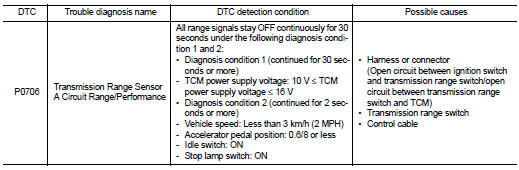
DTC DETECTION LOGIC
DTC CONFIRMATION PROCEDURE
1.PREPARATION BEFORE WORK
If another "DTC CONFIRMATION PROCEDURE" occurs just before, turn ignition switch OFF and wait for at least 10 seconds, then perform the next test.
>> GO TO 2.
2.PERFORM DTC CONFIRMATION PROCEDURE
1. Start the engine.
2. Maintain the following conditions.
Accelerator pedal position : 0.0/8
Brake pedal : Depressed
Vehicle speed : 0 km/h (0 MPH)
3. Shift the selector lever through entire positions from “P” to “L”. (Hold
the selector lever at each position for
35 seconds or more.)
4. Check the first trip DTC.
Is “P0706” detected? YES >> Go to TM-400, "Diagnosis Procedure".
NO >> INSPECTION END
Diagnosis Procedure
1.ADJUSTMENT OF CONTROL CABLE
Adjust the control cable. Refer to TM-383, "Inspection and Adjustment".
>> GO TO 2.
2.PERFORM DTC CONFIRMATION PROCEDURE
 With CONSULT-III
1. Turn ignition switch ON.
2. Select “Self Diagnostic Results” in “TRANSMISSION”.
3. Touch “Erase”.
4. Perform "DTC CONFIRMATION PROCEDURE". Refer to TM-400, "DTC Logic".
Is “P0706” detected? YES >> GO TO 3.
NO >> INSPECTION END
3.CHECK POWER CIRCUIT
1. Turn the ignition switch OFF.
2. Disconnect the transmission range switch connector.
3. Turn ignition switch ON.
4. Check the voltage between the transmission range switch harness connector and body ground.
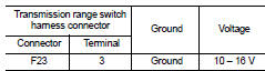
Is the check result normal? YES >> GO TO 4.
NO >> GO TO 7.
4.CHECK CIRCUIT BETWEEN TRANSMISSION RANGE SWITCH AND TCM (PART 1)
1. Turn the ignition switch OFF.
2. Disconnect the TCM connector.
3. Check the continuity between the transmission range switch harness connector and the TCM harness connector.
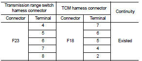
Is the check result normal? YES >> GO TO 5.
NO >> Repair or replace the malfunctioning parts.
5.CHECK CIRCUIT BETWEEN TRANSMISSION RANGE SWITCH AND TCM (PART 2)
Check the continuity between the transmission range switch harness connector and the TCM harness connector.
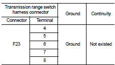
Is the check result normal? YES >> GO TO 6.
NO >> Repair or replace the malfunctioning parts.
6.CHECK TRANSMISSION RANGE SWITCH
Check the transmission range switch. Refer to TM-402, "Component Inspection (Transmission Range Switch)".
Is the check result normal? YES >> Check intermittent incident. Refer to GI-42, "Intermittent Incident".
NO >> Repair or replace the malfunctioning parts.
7.CHECK CIRCUIT BETWEEN IPDM E/R AND TRANSMISSION RANGE SWITCH (PART 1)
1. Disconnect the IPDM E/R connector.
2. Check the continuity between the IPDM E/R vehicle-side harness connector and the transmission range switch.
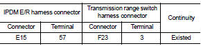
Is the check result normal? YES >> GO TO 8.
NO >> Repair or replace the malfunctioning parts.
8.CHECK CIRCUIT BETWEEN IPDM E/R AND TRANSMISSION RANGE SWITCH (PART 2)
Check the continuity between the IPDM E/R vehicle-side harness connector and the transmission range switch.
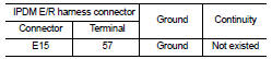
Is the check result normal? YES >> GO TO 9.
NO >> Repair or replace the malfunctioning parts.
9.DETECTION OF MALFUNCTION ITEMS
Check the following items: • Harness open circuit or short circuit between the ignition switch and IPDM E/R. Refer to PG-15, "Wiring Diagram - IGNITION POWER SUPPLY -".
• 10A fuse (No. 55, IPDM E/R). Refer to PG-25, "Fuse, Connector and Terminal Arrangement".
• IPDM E/R Is the check result normal? YES >> Check intermittent incident. Refer to GI-42, "Intermittent Incident".
NO >> Repair or replace the malfunctioning parts.
Component Inspection (Transmission Range Switch)
1.CHECK TRANSMISSION RANGE SWITCH
Check the continuity between the transmission range switch connector terminals.
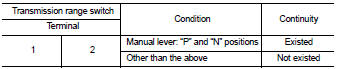
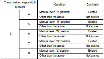
Is the inspection result normal? YES >> INSPECTION END
NO >> There is a malfunction of the transmission range switch. Replace the transaxle assembly. Refer to TM-508, "Removal and Installation".
 P0705 transmission range switch A
DTC Logic
DTC DETECTION LOGIC
DTC CONFIRMATION PROCEDURE
CAUTION:
Be careful of the driving speed.
1.PREPARATION BEFORE WORK
If another "DTC CONFIRMATION PROCEDURE" occurs just befor ...
 P0711 transmission fluid temperature sensor A
DTC Logic
DTC DETECTION LOGIC
DTC CONFIRMATION PROCEDURE
1.PREPARATION BEFORE WORK
If another "DTC CONFIRMATION PROCEDURE" occurs just before, turn ignition
switch OFF and wait for a ...
Other materials:
System
Starting system (with intelligent key) : System Diagram
*1: M/T models
*2: CVT models
Starting system (with intelligent key) : System Description
CVT MODELS
• When selector lever is P or N, power is supplied to starter relay and
starter control relay by transmission
range switch. And BCM ...
Warning lights and audible reminders
To help prevent the vehicle from moving unexpectedly by erroneous operation of
the Intelligent Key listed on the following chart or to help prevent the vehicle
from being stolen, chime or beep sounds inside and outside the vehicle and a warning
light illuminates or blinks.
When a chime or bee ...
Combination meter
Reference Value
VALUES ON THE DIAGNOSIS TOOL
NOTE:
Some items are not available according to vehicle specification.
TERMINAL LAYOUT
PHYSICAL VALUES
Fail-Safe
FAIL-SAFE
The combination meter activates the fail-safe control if CAN communication
with each unit is malfuncti ...
