Nissan Juke Service and Repair Manual : System
Starting system (with intelligent key) : System Diagram
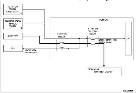
*1: M/T models
*2: CVT models
Starting system (with intelligent key) : System Description
CVT MODELS
• When selector lever is P or N, power is supplied to starter relay and starter control relay by transmission range switch. And BCM and IPDM E/R (CPU) detect selector lever P/N condition by the inputted signal.
• When starter operating condition is satisfied, IPDM E/R turns starter control relay ON by starter control relay control signal.
• When engine cranking condition is satisfied, BCM turns starter relay ON by starter control relay control signal.
• Then battery power is supplied to starter motor (“S” terminal) through starter control relay and starter relay.
M/T MODELS
• When the ignition switch is turned ON or START position power is supplied to starter relay and starter control relay. And BCM and IPDM E/R (CPU) detect ignition switch position by the inputted signal.
• When starter operating condition is satisfied, IPDM E/R turns starter control relay ON by starter control relay control signal.
• When engine cranking condition is satisfied, BCM turns starter relay ON by starter control relay control signal.
• Then battery power is supplied to starter motor (“S” terminal) through starter control relay and starter relay.
Starting system (without intelligent key) : System Diagram
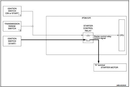
*1: M/T models
*2: CVT model
Starting system (without intelligent key) : System Description
CVT MODELS
• When selector lever is P or N, power is supplied to starter control relay by transmission range switch. And IPDM E/R (CPU) detect selector lever P/N condition by the inputted signal.
• When engine cranking condition is satisfied, then battery power is supplied to starter motor (“S” terminal) through starter control relay.
M/T MODELS
When ignition switch is START position, battery power is supplied to starter motor (“S” terminal).
 Component parts
Starting system (with intelligent key) : Component Parts Location
1. IPDM E/R
Refer to PCS-5, "Component Parts
Location".
2. Transmission range switch (CVT
models)
Refer to TM-131, & ...
 Wiring diagram
...
Other materials:
Removal and installation
ALTERNATOR
HR16DE
HR16DE : Exploded View
REMOVAL
1. Alternator bracket mounting bolt
2. Alternator bracket
3. Alternator mounting bolt
4. Alternator
5. “B” terminal harness
6. “B” terminal nut
7. Alternator connector
: N·m (kg-m, ft-lb)
DISASSEMBLY
Type: A002TJ1291ZE
1 ...
Hood
WARNING
• Make sure the hood is completely closed and latched before driving.
Failure to do so could cause the hood to fly open and result in an accident.
• If you see steam or smoke coming from the engine compartment, to avoid injury
do not open the hood.
When opening the hood:
1. Pull ...
Driver air bag module
Exploded View
1. Steering column upper cover
2. Steering column assembly
3. Steering column lower cover
4. Side lid LH
5. TORX bolt
6. Driver air bag module
7. TORX bolt
8. Side lid RH
9. Steering wheel
10. Spiral cable
11. Steering angle sensor
12. Combination switch
13. Stee ...
