Nissan Juke Service and Repair Manual : CVT control system
Wiring diagram
For connector terminal arrangements, harness layouts, and alphabets in a
(option abbreviation; if not
described in wiring diagram), refer to GI-12, "Connector Information/Explanation
of Option Abbreviation".
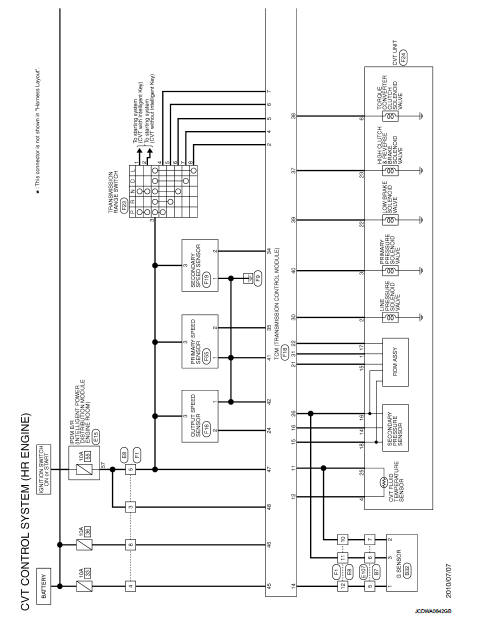
 Wiring diagram
...
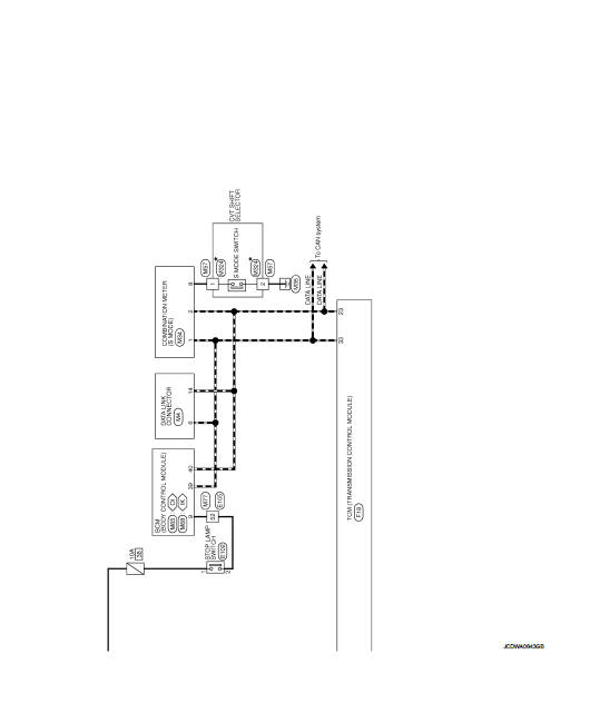
 CVT shift lock system
Wiring diagram
connector terminal arrangements, harness layouts, and alphabets in a
(option abbreviation; if not
described in wiring diagram), refer to GI-12, "Connector Information/Explanatio ...
Other materials:
P0225 APP sensor
DTC Logic
DTC DETECTION LOGIC
NOTE:
• If DTC P0225 is displayed with DTC P0641, first perform trouble diagnosis for
DTC P0641. Refer to
EC-974, "DTC Logic".
Diagnosis Procedure
1.CHECK GROUND CONNECTIONS
1. Turn ignition switch OFF.
2. Check ground connection E38. Refer to Gr ...
Hazard reminder operation does not operate
Diagnosis Procedure
1.CHECK DTC WITH BCM AND COMBINATION METER
Check that DTC is not detected with BCM and combination meter.
Is the inspection result normal?
YES >> GO TO 2.
NO-1 >> Refer to BCS-141, "DTC Index". (BCM)
NO-2 >> Refer to MWI-36, "DTC Index&q ...
B1130 side air bag module RH
DTC Logic
DTC DETECTION LOGIC
DTC CONFIRMATION PROCEDURE
1.CHECK SELF-DIAG RESULT
With CONSULT-III
1. Turn ignition switch ON.
2. Perform “Self Diagnostic Result” mode of “AIR BAG” using CONSULT-III.
Without CONSULT-III
1. Turn ignition switch ON.
2. Check the air bag warning la ...
