Nissan Juke Service and Repair Manual : Front fog lamp circuit
Component Function Check
1.CHECK FRONT FOG LAMP OPERATION
 CONSULT-III ACTIVE TEST
1. Select ŌĆ£EXTERNAL LAMPSŌĆØ of IPDM E/R active test item.
2. With operating the test items, check that the front fog lamp is turned ON.
Fog : Front fog lamp ON Off : Front fog lamp OFF
Is the measurement normal? YES >> Front fog lamp circuit is normal.
NO >> Refer to EXL-54, "Diagnosis Procedure".
Diagnosis Procedure
1
.CHECK FRONT FOG LAMP FUSE
1. Turn ignition switch OFF.
2. Check that the following fuse is not fusing.

Is the inspection result normal? YES >> GO TO 3.
NO >> GO TO 2.
2.CHECK FRONT FOG LAMP SHORT CIRCUIT
1. Disconnect front fog connector and IPDM E/R connector.
2. Check continuity between IPDM E/R harness connector and ground.
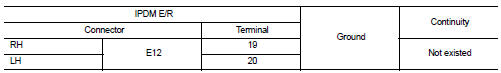
Is the inspection result normal? YES >> Replace fuse. (Replace IPDM E/R if the fuse is fusing again.) NO >> Repair or replace harness. And then replace the fuse.
3.CHECK FRONT FOG LAMP BULB
Check the applicable lamp bulb.
Is the inspection result normal? YES >> GO TO 4.
NO >> Replace bulb.
4.CHECK FRONT FOG LAMP OUTPUT VOLTAGE
 CONSULT-III ACTIVE TEST
1. Disconnect front fog lamp connector.
2. Turn ignition switch ON.
3. Select ŌĆ£EXTERNAL LAMPSŌĆØ of IPDM E/R active test item.
4. With operating the test items, check the voltage between IPDM E/R harness connector and ground.
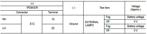
Is the inspection result normal? YES >> GO TO 5.
NO >> Replace IPDM E/R.
5.CHECK FRONT FOG LAMP OPEN CIRCUIT
1. Turn ignition switch OFF.
2. Disconnect IPDM E/R connector.
3. Check continuity between IPDM E/R harness connector and front fog lamp harness connector.
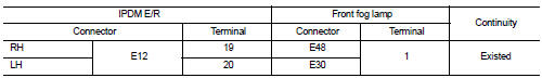
Is the inspection result normal? YES >> GO TO 6.
NO >> Repair or replace harness.
6.CHECK FRONT FOG LAMP GROUND CIRCUIT OPEN CIRCUIT
Check continuity between front fog lamp harness connector and grou
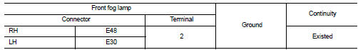
Is the inspection result normal? YES >> Refer to GI-42, "Intermittent Incident".
NO >> Repair or replace harness.
 Headlamp aiming system (manual)
Component Inspection
1.CHECK HEADLAMP AIMING SWITCH
1. Remove headlamp aiming switch.
2. Check resistance among each headlamp aiming switch terminal.
Is the inspection result normal?
YES >&g ...
 Rear fog lamp circuit
Component Function Check
1.CHECK REAR FOG LAMP OPERATION
CONSULT-III ACTIVE TEST
1. Select ŌĆ£RR FOG LAMPŌĆØ of BCM (HEAD LAMP) active test item.
2. With operating the test items, check that the r ...
Other materials:
P2122, P2123 APP sensor
DTC Logic
DTC DETECTION LOGIC
NOTE:
If DTC P2122 or P2123 is displayed with DTC P0643, first perform the trouble
diagnosis for DTC P0643.
Refer to EC-686, "DTC Logic".
DTC CONFIRMATION PROCEDURE
1.PRECONDITIONING
If DTC Confirmation Procedure has been previously conducted, alw ...
B1144 diagnosis sensor unit
DTC Logic
DTC DETECTION LOGIC
DTC CONFIRMATION PROCEDURE
1.CHECK SELF-DIAG RESULT
With CONSULT-III
1. Turn ignition switch ON.
2. Perform ŌĆ£Self Diagnostic ResultŌĆØ mode of ŌĆ£AIR BAGŌĆØ using CONSULT-III.
Without CONSULT-III
1. Turn ignition switch ON.
2. Check the air bag warning la ...
Precaution for Liquid Gasket
REMOVAL OF LIQUID GASKET
ŌĆó After removing the mounting bolts and nuts, separate the mating
surface using a seal cutter and remove the liquid gasket.
CAUTION:
Be careful not to damage the mating surfaces.
ŌĆó In areas where the cutter is difficult to use, use a plastic hammer to
lightly tap ...
