Nissan Juke Service and Repair Manual : Oil filter
Removal and Installation
REMOVAL
1. Remove engine under cover.
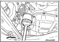
2. Using oil filter wrench [SST: KV10115801 (J-38956)] (A), remove oil filter.
 : Vehicle front
CAUTION:
• Oil filter is provided with relief valve. Use genuine NISSAN
oil filter or equivalent.
• Be careful not to get burned when engine and engine oil may be hot.
• When removing, prepare a shop cloth to absorb any engine oil leakage or spillage.
• Completely wipe off any engine oil that adheres to engine and vehicle.
INSTALLATION
1. Remove foreign materials adhering to the oil filter installation surface.
2. Apply new engine oil to the oil seal contact surface of new oil filter.
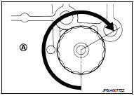
3. Screw oil filter manually until it touches the installation surface, then tighten it by 2/3 turn (A). Or tighten to specification.
Oil filter:
 : 17.7 N·m (1.8 kg-m, 13 ft-lb)
Inspection
INSPECTION AFTER INSTALLATION
1. Check the engine oil level. Refer to LU-8, "Inspection".
2. Start the engine, and check that there is no leakage of engine oil.
3. Stop the engine and wait for 10 minutes.
4. Check the engine oil level, and adjust the level. Refer to LU-8, "Inspection".
 Engine oil
Inspection
ENGINE OIL LEVEL
NOTE:
Before starting engine, put vehicle horizontally and check the engine oil level.
If engine is already started, stop
it and allow 10 minutes before checking.
...
 Removal and installation
OIL COOLER ...
Other materials:
P1811 power supply circuit for 4wd control module
DTC Logic
DTC DETECTION LOGIC
DTC CONFIRMATION PROCEDURE
1.PRECONDITIONING
If “DTC CONFIRMATION PROCEDURE” has been previously conducted, always turn
ignition switch OFF and
wait at least 10 seconds before conducting the next test.
>> GO TO 2.
2.DTC REPRODUCTION PROCEDURE
W ...
Brake fluid level switch
Component Function Check
1.CHECK BRAKE FLUID LEVEL SWITCH OPERATION
When the brake fluid is full or empty. Then check that the brake warning lamp
in the combination meter turns
ON/OFF correctly.
Is the inspection result normal?
YES >> INSPECTION END
NO >> Proceed to BRC-72, &qu ...
P0703 brake switch B
Description
BCM detects ON/OFF state of the stop lamp switch and transmits the data to
the CVT control unit via CAN
communication by converting the data to a signal.
DTC Logic
DTC DETECTION LOGIC
DTC CONFIRMATION PROCEDURE
CAUTION:
Always drive vehicle at a safe speed.
NOTE:
If “DTC C ...
