Nissan Juke Service and Repair Manual : Door motor
Diagnosis Procedure
NOTE
:
If all of door motor DTCs are detected, check this circuit.
1.CHECK DOOR MOTOR POWER SUPPLY
1. Turn ignition switch ON.
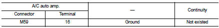
2. Check voltage between intake door motor harness connector and ground.
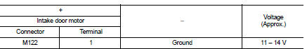
Is the inspection result normal? YES >> GO TO 2.
NO >> GO TO 7.
2.CHECK DOOR MOTOR GROUND CIRCUIT FOR OPEN
1. Turn ignition switch OFF.
2. Disconnect intake door motor and A/C auto amp. connector.
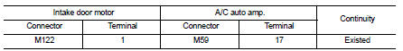
3. Check continuity between intake door motor harness connector and A/C auto amp. harness connector.
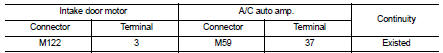
Is the inspection result normal? YES >> GO TO 3.
NO >> Repair harness or connector.
3.CHECK DOOR MOTOR LIN SIGNAL
1. Connect A/C auto amp. and intake door motor connector.
2. Turn ignition switch ON.
3. Confirm output waveform between A/C auto amp. harness connector and ground using oscilloscope.
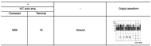
Is the inspection result normal? YES >> GO TO 4.
NO >> GO TO 6.
4.CHECK DOOR MOTOR LIN SIGNAL CIRCUIT FOR OPEN
1. Turn ignition switch OFF.
2. Disconnect A/C auto amp. and intake door motor connector.
3. Check continuity between A/C auto amp. harness connector and intake door motor harness connector.
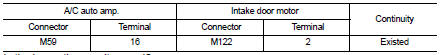
Is the inspection result normal? YES >> GO TO 5.
NO >> Repair harness or connector.
5.CHECK INTERMITTENT INCIDENT
Check intermittent incident. Refer to GI-42, "Intermittent Incident".
>> INSPECTION END
6.CHECK DOOR MOTOR LIN SIGNAL CIRCUIT FOR SHORT
1. Turn ignition switch OFF.
2. Disconnect following connectors.
- A/C auto amp.
- Air mix door motor
- Mode door motor
- Intake door motor
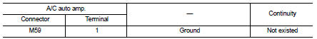
3. Check continuity between A/C auto amp. harness connector and ground.
Is the inspection result normal? YES >> Replace A/C auto amp. Refer to HAC-188, "Removal and Installation".
NO >> Repair harness or connector.
7.CHECK DOOR MOTOR POWER SUPPLY CIRCUIT FOR OPEN
1. Turn ignition switch OFF.
2. Disconnect intake door motor and A/C auto amp. connector.
3. Check continuity between intake door motor harness connector and A/C auto amp. harness connector.
Is the inspection result normal? YES >> GO TO 8.
NO >> Repair harness or connector.
8.CHECK DOOR MOTOR POWER SUPPLY CIRCUIT FOR SHORT
1. Disconnect following connectors.
- Air mix door motor
- Mode door motor
2. Check continuity between A/C auto amp. harness connector and ground.
Is the inspection result normal? YES >> Replace A/C auto amp. Refer to HAC-188, "Removal and Installation".
NO >> Repair harness or connector.
 Power supply and ground circuit
A/C auto AMP. : Diagnosis Procedure
1.CHECK SYMPTOM
Check symptom (A or B).
Which symptom is detected?
A >>GO TO 2.
B >>GO TO 5.
2.CHECK FUSE
1. Turn ignition switch OFF.
2. ...
 A/C on signal
Component Function Check
1.CHECK A/C ON SIGNAL
With CONSULT-III
1. Turn ignition switch ON.
2. Operate blower motor.
3. Select “AIR CONDITIONER” of “BCM” using CONSULT-III.
4. Select “ ...
Other materials:
Side oil seal
Exploded View
1. Rear final drive assembly
2. Side oil seal (right)
3. Electric controlled coupling (right)
4. Reamer bolt
5. Side oil seal (left)
6. Electric controlled coupling (left)
A. Oil seal lip B. Gear carrier mouting face
: Vehicle front
: N·m (kg-m, ft-lb)
: Always replace ...
IGN off interlock door unlock function does not operate
Diagnosis Procedure
1.CHECK “AUTOMATIC LOCK/UNLOCK SELECT” SETTING IN “WORK SUPPORT”
1. Select “DOOR LOCK” of “BCM” using CONSULT-III.
2. Select “AUTOMATIC LOCK/UNLOCK SELECT” in “WORK SUPPORT” mode.
3. Check “AUTOMATIC LOCK/UNLOCK SELECT” in “WORK SUPPORT”.
Re ...
B2193 chain of ECM-IMMU
DTC Logic
DTC DETECTION LOGIC
NOTE:
• If DTC B2193 is displayed with DTC U1000, first perform the trouble diagnosis
for DTC U1000. Refer to
BCS-153, "DTC Logic".
• If DTC B2193 is displayed with DTC U1010, first perform the trouble diagnosis
for DTC U1010. Refer to
BCS-154, & ...
