Nissan Juke Service and Repair Manual : U1117 lost communication (ABS)
Description
CAN (Controller Area Network) is a serial communication line for real-time application. It is an on-vehicle multiplex communication line with high data communication speed and excellent malfunction detection ability.
Many electronic control units are equipped onto a vehicle, and each control unit shares information and links with other control units during operation (not independently). In CAN communication, control units are connected with 2 communication lines (CAN-H line, CAN-L line) allowing a high rate of information transmission with less wiring. Each control unit transmits/receives data but selectively reads required data only.
DTC Logic
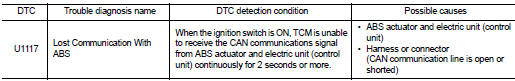
DTC DETECTION LOGIC
DTC CONFIRMATION PROCEDURE
1.PREPARATION BEFORE WORK
If another "DTC CONFIRMATION PROCEDURE" occurs just before, turn ignition switch OFF and wait for at least 10 seconds, then perform the next test.
>> GO TO 2.
2.PERFORM DTC CONFIRMATION PROCEDURE
 With CONSULT-III
1. Start the engine and wait for 5 seconds or more.
2. Check the DTC.
Is “U1117” detected? YES >> Go to TM-384, "Diagnosis Procedure".
NO >> INSPECTION END
Diagnosis Procedure
For the diagnosis procedure, refer to LAN-17, "Trouble Diagnosis Flow Chart".
 U1000 can comm circuit
Description
CAN (Controller Area Network) is a serial communication line for real-time
application. It is an on-vehicle multiplex
communication line with high data communication speed and excellen ...
 U1119 lost comm (multi-display)
Description
CAN (Controller Area Network) is a serial communication line for real-time
application. It is an on-vehicle multiplex
communication line with high data communication speed and excellen ...
Other materials:
Loss of power
Description
CHART 12: LOSS OF POWER
Diagnosis Procedure
1.CHECK FUEL
Check that the fuel reservoir is correctly filled and with the right fuel.
>> GO TO 2.
2.CHECK FUEL FILTER
Check the correctness of the fuel filter.
Is the fuel filter correct?
Yes >> GO TO 3.
No >& ...
Precaution Necessary for Steering Wheel Rotation after Battery Disconnect
NOTE:
• Before removing and installing any control units, first turn the ignition
switch to the LOCK position, then disconnect
both battery cables.
• After finishing work, confirm that all control unit connectors are connected
properly, then re-connect both
battery cables.
• Always us ...
Additional service when replacing ECM
Description
When replacing ECM, this procedure must be performed.
Work Procedure
1.PRECONDITIONING
• Connect a CONSULT-III
• Connect a battery charger
• Electric load switch is OFF
• Wait for the engine to cool [engine coolant temperature < 60?°C (140?°F) and air
temperature &l ...
