Nissan Juke Service and Repair Manual : U1000 can comm circuit
Description
CAN (Controller Area Network) is a serial communication line for real-time application. It is an on-vehicle multiplex communication line with high data communication speed and excellent malfunction detection ability.
Many electronic control units are equipped onto a vehicle, and each control unit shares information and links with other control units during operation (not independently). In CAN communication, control units are connected with 2 communication lines (CAN-H line, CAN-L line) allowing a high rate of information transmission with less wiring. Each control unit transmits/receives data but selectively reads required data only.
DTC Logic
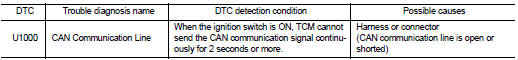
DTC DETECTION LOGI
DTC CONFIRMATION PROCEDURE
1.PREPARATION BEFORE WORK
If another “DTC CONFIRMATION PROCEDURE” occurs just before, turn ignition switch OFF and wait for at least 10 seconds, then perform the next test.
>> GO TO 2.
2.CHECK DTC DETECTION
 With CONSULT-III
1. Start the engine and wait for at least 5 seconds.
2. Check the DTC.
Is “U1000” detected? YES >> Go to TM-390, "Diagnosis Procedure".
NO >> INSPECTION END
Diagnosis Procedure
For the diagnosis procedure, refer to LAN-17, "Trouble Diagnosis Flow Chart".
 U0300 can communication data
Description
CAN (Controller Area Network) is a serial communication line for real-time
application. It is an on-vehicle multiplex
communication line with high data communication speed and excellen ...
 U1117 lost communication (ABS)
Description
CAN (Controller Area Network) is a serial communication line for real-time
application. It is an on-vehicle multiplex
communication line with high data communication speed and excellen ...
Other materials:
Explanation of scheduled maintenance items
The following detailed descriptions are designed to provide you with a comprehensive understanding of the scheduled maintenance items that require periodic inspection or replacement to keep your Nissan Leaf running at its peak. Your official maintenance schedule serves as a roadmap, explicitly indic ...
Power supply and ground circuit
A/C auto AMP. : Diagnosis Procedure
1.CHECK SYMPTOM
Check symptom (A or B).
Which symptom is detected?
A >>GO TO 2.
B >>GO TO 5.
2.CHECK FUSE
1. Turn ignition switch OFF.
2. Check 10A fuse (No. 3, located in fuse block (J/B)].
NOTE:
Refer to PG-22, "Fuse, Connector ...
If the Li-ion battery becomes completely discharged
Should the power limitation indicator light
illuminate while you are driving your Nissan Leaf, be aware that the system has restricted the output of the traction motor. This is an intentional safety feature designed to preserve remaining energy, and you will notice a correspondin ...
