Nissan Juke Service and Repair Manual : C1144 incomplete steering angle sensor adjustment
DTC Logic
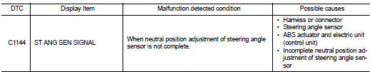
DTC DETECTION LOGIC
DTC CONFIRMATION PROCEDURE
1.PRECONDITIONING
If “DTC CONFIRMATION PROCEDURE” has been previously conducted, always turn ignition switch OFF and wait at least 10 seconds before conducting the next test.
>> GO TO 2.
2.CHECK DTC DETECTION
 With CONSULT-III.
1. Turn the ignition switch OFF to ON.
2. Perform self-diagnosis for “ABS”.
Is DTC “C1144” detected? YES >> Proceed to BRC-191, "Diagnosis Procedure".
NO >> INSPECTION END
Diagnosis Procedure
1.ADJUST THE NEUTRAL POSITION OF STEERING ANGLE SENSOR
Perform neutral position adjustment of steering angle sensor. Refer to BRC-149, "Work Procedure".
>> GO TO 2.
2.CHECK ABS ACTUATOR AND ERECTRIC UNIT (CONTROL UNIT)
 With CONSULT-III.
Perform self-diagnosis for “ABS”.
Is DTC “C1144” detected? YES >> GO TO 3.
NO >> INSPECTION END
3.CHECK STEERING ANGLE SENSOR SYSTEM
1. Turn the ignition switch OFF.
2. Check steering angle sensor system. Refer to BRC-189, "Diagnosis Procedure".
Is the inspection result normal? YES >> Replace ABS actuator and electric unit (control unit). Refer to BRC-233, "Removal and Installation".
NO >> Repair or replace error-detected parts.
 C1143 steering angle sensor
DTC Logic
DTC DETECTION LOGIC
DTC CONFIRMATION PROCEDURE
1.PRECONDITIONING
If “DTC CONFIRMATION PROCEDURE” has been previously conducted, always turn
ignition switch OFF and
wait at least ...
 C1155 brake fluid level switch
DTC Logic
DTC DETECTION LOGIC
DTC CONFIRMATION PROCEDURE
1.PRECONDITIONING
If “DTC CONFIRMATION PROCEDURE” has been previously conducted, always turn
ignition switch OFF and
wait at least ...
Other materials:
Radiator cap : Inspection
Check valve seat (A) of radiator cap.
B : Metal plunger
- Check that valve seat is swollen to the extent that the edge of the
plunger cannot be seen when watching it vertically from the top.
- Check that valve seat has no soil and damage.
Pull negative-pressure valve to open it, and that it c ...
Front door lock
Exploded View
1. Door key cylinder assembly (driver
side)
Outside handle escutcheon (passenger
side)
2. Rear gasket
3. Outside handle bracket
4. TORX bolt
5. Key rod (driver side)
6. Door lock assembly
7. Inside handle
8. Outside handle
9. Front gasket
10. Cable clip
: Pawl
: V ...
P1612 chain of ECM-IMMU
DTC Logic
DTC DETECTION LOGIC
NOTE:
• If DTC P1612 is displayed with DTC U1000 (for BCM), first perform the trouble
diagnosis for DTC U1000.
Refer to BCS-153, "DTC Logic".
• If DTC P1612 is displayed with DTC U1010 (for BCM), first perform the trouble
diagnosis for DTC U1010 ...
