Nissan Juke Service and Repair Manual : C1143 steering angle sensor
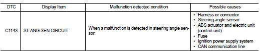
DTC Logic
DTC DETECTION LOGIC
DTC CONFIRMATION PROCEDURE
1.PRECONDITIONING
If ŌĆ£DTC CONFIRMATION PROCEDUREŌĆØ has been previously conducted, always turn ignition switch OFF and wait at least 10 seconds before conducting the next test.
>> GO TO 2.
2.CHECK DTC DETECTION
 With CONSULT-III.
1. Turn the ignition switch OFF to ON.
2. Perform self-diagnosis for ŌĆ£ABSŌĆØ.
Is DTC ŌĆ£C1143ŌĆØ detected? YES >> Proceed to BRC-189, "Diagnosis Procedure".
NO >> INSPECTION END
Diagnosis Procedure
1.CHECK STEERING ANGLE SENSOR POWER SUPPLY
1. Turn the ignition switch OFF.
2. Disconnect steering angle sensor harness connector.
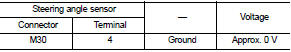
3. Check voltage between steering angle sensor harness connector and ground.
4. Turn the ignition switch ON.
CAUTION:
Never start engine.
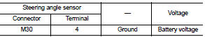
5. Check voltage between steering angle sensor harness connector and ground.
Is the inspection result normal? YES >> GO TO 3.
NO >> GO TO 2.
2.CHECK STEERING ANGLE SENSOR POWER SUPPLY CIRCUIT
1. Turn the ignition switch OFF.
2. Check 10 A fuse (#3).
3. Check continuity and short circuit between steering angle sensor harness connector terminal (4) and 10 A fuse (#3).
Is the inspection result normal? YES >> Perform trouble diagnosis for ignition power supply. Refer to PG-15, "Wiring Diagram - IGNITION POWER SUPPLY -".
NO >> Repair or replace error-detected parts.
3.CHECK STEERING ANGLE SENSOR GROUND CIRCUIT
1. Turn the ignition switch OFF.
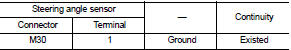
2. Check continuity between steering angle sensor harness connector and ground.
Is the inspection result normal? YES >> GO TO 4.
NO >> Repair or replace error-detected parts.
4.CHECK TERMINAL
Check steering angle sensor pin terminals for damage or loose connection with harness connector.
Is the inspection result normal? YES >> GO TO 5.
NO >> Repair or replace error-detected parts.
5.CHECK CAN COMMUNICATION LINE
Check ŌĆ£STRG BRANCH LINE CIRCUITŌĆØ. Refer to LAN-51, "Diagnosis Procedure".
Is the inspection result normal? YES >> Replace ABS actuator and electric unit (control unit). Refer to BRC-233, "Removal and Installation".
NO >> Repair or replace error-detected parts. Refer to BRC-96, "Precaution for Harness Repair".
 C1142 press sensor
DTC Logic
DTC DETECTION LOGIC
DTC CONFIRMATION PROCEDURE
1.PRECONDITIONING
If ŌĆ£DTC CONFIRMATION PROCEDUREŌĆØ has been previously conducted, always turn
ignition switch OFF and
wait at least ...
 C1144 incomplete steering angle sensor adjustment
DTC Logic
DTC DETECTION LOGIC
DTC CONFIRMATION PROCEDURE
1.PRECONDITIONING
If ŌĆ£DTC CONFIRMATION PROCEDUREŌĆØ has been previously conducted, always turn
ignition switch OFF and
wait at least ...
Other materials:
P1556, P1557 battery temperature sensor
DTC Logic
DTC DETECTION LOGIC
DTC CONFIRMATION PROCEDURE
1.PRECONDITIONING
1. Turn ignition switch OFF and wait at least 10 seconds.
2. Turn ignition switch ON.
3. Turn ignition switch OFF and wait at least 10 seconds.
TESTING CONDITION:
Before performing the following procedure, confirm ...
Speedometer and odometer
Speedometer
The speedometer indicates vehicle speed in miles per hour (MPH) and kilometers
per hour (km/h).
Odometer/twin trip odometer
The odometer 1 /twin trip odometer 2 are displayed when the ignition switch is
in the ON position.
The odometer records the total distance the vehicle h ...
Refrigerant
Description
CONNECTION OF SERVICE TOOLS AND EQUIPMENT
1. Shut-off valve
2. A/C service valve
3. Recovery/recycling/recharging
equipment
4. Vacuum pump
5. Manifold gauge set
6. Refrigerant container (HFC-134a)
7. Weight scale
A. Preferred (best) method
B. Alternative method
C. For ...
