Nissan Juke Service and Repair Manual : C1142 press sensor
DTC Logic
DTC DETECTION LOGIC
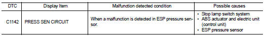
DTC CONFIRMATION PROCEDURE
1.PRECONDITIONING
If “DTC CONFIRMATION PROCEDURE” has been previously conducted, always turn ignition switch OFF and wait at least 10 seconds before conducting the next test.
>> GO TO 2.
2.CHECK DTC DETECTION
 With CONSULT-III.
1. Turn the ignition switch OFF to ON.
2. Perform self-diagnosis for “ABS”.
Is DTC “C1142” detected? YES >> Proceed to BRC-186, "Diagnosis Procedure".
NO >> INSPECTION END
Diagnosis Procedure
1.CHECK ABS ACTUATOR AND ELECTRIC UNIT (CONTROL UNIT) POWER SUPPLY SYSTEM
Check ABS actuator and electric unit (control unit) power supply system. Refer to BRC-205, "Diagnosis Procedure".
Is the inspection result normal? YES >> GO TO 2.
NO >> Repair or replace error-detected parts.
2.CHECK BRAKE FLUID LEACKAGE
Check brake fluid leakage.
• LHD: Refer to BR-12, "Inspection".
• RHD: Refer to BR-80, "Inspection".
Is the inspection result normal? YES >> GO TO 3.
NO >> Repair or replace error-detected parts.
3.CHECK CONNECTOR
1. Turn ignition switch OFF.
2. Check ABS actuator and electric unit (control unit) harness connector for disconnection or looseness.
3. Check ESP pressure sensor harness connector for disconnection or looseness.
Is the inspection result normal? YES >> GO TO 4.
NO >> Repair or replace error-detected parts, securely lock the connector, and GO TO 4.
4.PERFORM SELF-DIAGNOSIS
Perform self-diagnosis for “ABS” again.
Is DTC“C1142” detected? YES >> GO TO 5.
NO >> INSPECTION END 5.CHECK ESP PRESSURE SENSOR CIRCUIT
1. Turn ignition switch OFF.
2. Disconnect ABS actuator and electric unit (control unit) harness connector.
3. Disconnect ESP pressure sensor harness connector.
4. Check continuity between ESP pressure sensor harness connector and ABS actuator and electric unit (control unit) harness connecto
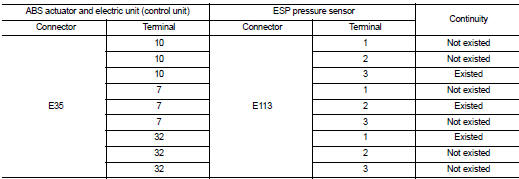
Is the inspection result normal? YES >> GO TO 6.
NO >> Repair or replace error-detected parts.
6.CHECK ESP PRESSURE SENSOR POWER SUPPLY
1. Connect ABS actuator and electric unit (control unit) harness connector.
2. Turn the ignition switch ON.
CAUTION:
Never start the engine.
3. Check voltage ESP pressure sensor harness connector terminals.
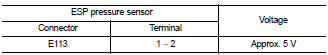
Is the inspection result normal? YES >> GO TO 7.
NO >> Replace ABS actuator and electric unit (control unit). Refer to BRC-233, "Removal and Installation".
7.CHECK ESP PRESSURESENSOR (1)
1. Turn ignition switch OFF.
2. Secure connect ESP pressure sensor harness connector.
3. Check loose connection with harness connector.
4. Turn ignition switch ON.
CAUTION:
Never start the engine.
5. In 1 second or more after ignition switch ON, check pressure sensor voltage.
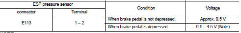
NOTE:
Voltage changes according to the degree of the application of the brake pedal.
Is the inspection result normal? YES >> Replace ABS actuator and electric unit (control unit). Refer to BRC-233, "Removal and Installation".
NO >> Replace ESP pressure sensor.
• LHD: Refer to BR-24, "FRONT : Exploded View".
• RHD: Refer to BR-91, "FRONT : Exploded View".
 C1140 actuator relay system
DTC Logic
DTC DETECTION LOGIC
DTC CONFIRMATION PROCEDURE
1.PRECONDITIONING
If “DTC CONFIRMATION PROCEDURE” has been previously conducted, always turn
ignition switch OFF and
wait at least ...
 C1143 steering angle sensor
DTC Logic
DTC DETECTION LOGIC
DTC CONFIRMATION PROCEDURE
1.PRECONDITIONING
If “DTC CONFIRMATION PROCEDURE” has been previously conducted, always turn
ignition switch OFF and
wait at least ...
Other materials:
P1616 ECM
DTC Logic
DTC DETECTION LOGIC
DTC CONFIRMATION PROCEDURE
1.PERFORM DTC CONFIRMATION PROCEDURE FOR MALFUNCTION
1. Turn ignition switch ON amd wait 2 seconds or more.
2. Check DTC in “Self Diagnostic Result” mode of “ENGINE” using CONSULT-III.
Is DTC detected?
YES >> Go to SEC ...
e-Pedal system
WARNING
Never rely solely on the innovative e-Pedal system to manage your speed or bring the vehicle to a halt, as there is a clear physical performance limit to the system's automated deceleration functions. Always drive carefully, maintain full situational awareness, and remain highly attenti ...
Wiper and washer system symptoms
With rain sensor
WITH RAIN SENSOR : Symptom Table
Without rain sensor
WITHOUT RAIN SENSOR : Symptom Table
...
