Nissan Juke Service and Repair Manual : Cooling fan
Exploded View
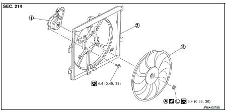
1. Fan motor
2. Fan shroud
3. Cooling fan
A. Apply on fan motor shaft
 : N·m (kg-m, in-lb)
 : Apply genuine high strength thread
locking sealant or equivalent.
Removal and Installation
REMOVAL
1. Drain engine coolant. Refer to CO-11, "Draining".
CAUTION:
• Perform this step engine is cold.
• Never spill engine coolant on drive belt.
2. Remove engine cover.
3. Remove front bumper. Refer to EXT-12, "Exploded View".
4. Remove radiator core support upper. Refer to DLK-149, "MR16DDT : Exploded View".
5. Disconnect cooling fan harness connector.
6. Remove reservoir tank. Refer to CO-17, "Exploded View".
7. Remove radiator hose (upper). Refer to CO-17, "Exploded View".
8. Remove cooling fan assembly.
CAUTION:
Be careful not to damage or scratch on radiator core when removing.
INSTALLATION
Note the following, and install in the reverse order of removal.
CAUTION:
Only use genuine parts for fan shroud mounting bolt and observe the specified
torque (to prevent
radiator from being damaged).
NOTE:
Cooling fan is controlled by ECM. For details, Refer to EC-774, "Component Function Check".
Disassembly and Assembly
DISASSEMBLY
1. Remove cooling fan mounting nut, and then remove the cooling fan.
2. Remove fan motor.
ASSEMBLY
Note the following, and assemble in the reverse order of disassembly.
• Apply genuine high strength thread locking sealant on fan motor shaft.
Inspection
Cooling Fan
Inspect cooling fan for crack or unusual bend.
• If anything is found, replace cooling fan.
 Radiator
Exploded View
1. Cooling fan assembly
2. Mounting rubber (upper)
3. Radiator
4. Mounting rubber (lower)
5. O-ring 6. Drain plug
7. Clamp 8. Radiator hose (lower) (LH)
9. Reservoir tank h ...
 Water pump
Exploded View
1. Gasket
2. Water pump
: N·m (kg-m, ft-lb)
: Always replace after every
disassembly.
Removal and Installation
REMOVAL
1. Drain engine coolant from radiator. Refer to CO-11, ...
Other materials:
Removal and Installation
CAUTION:
• Be sure to use genuine exhaust system parts or equivalents which are specially
designed for heat
resistance, corrosion resistance and shape.
• Perform the operation with the exhaust system fully cooled down because the
system is still hot just
after the engine stops.
• Be c ...
Condenser
Exploded View
1. Condenser
2. Condenser lower bracket RH
3. Condenser lower bracket LH
4. O-ring
5. Liquid tank braket
6. Liquid tank
7. Braket
8. O-ring
9. Refrigerant pressure sensor
: Do not reuse
: N·m (kg-m, in-lb)
: N·m (kg-m, ft-lb)
Condenser : Removal and Installation
...
ECU diagnosis information
ABS actuator and electric unit (control unit)
Reference Value
CONSULT-III DATA MONITOR STANDARD VALUE
*1: Confirm tire pressure is standard value.
*2: Refer to “valve operation” in BRC-13, "System Description" for valve
operation of each valve.
*3: Refer to BRC-13, "Sys ...
