Nissan Juke Service and Repair Manual : Water pump
Exploded View
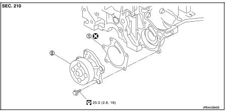
1. Gasket
2. Water pump
 : N·m (kg-m, ft-lb)
 : Always replace after every
disassembly.
Removal and Installation
REMOVAL
1. Drain engine coolant from radiator. Refer to CO-11, "Draining".
CAUTION:
• Perform this step when the engine is cold.
• Never spill engine coolant on drive belt.
2. Steer front wheel to the right.
3. Remove front fender protector (RH). Refer to EXT-22, "Exploded View".
4. Remove drive belt. Refer to EM-155, "Removal and Installation".
5. Remove water pump.
• Engine coolant will leak from cylinder block, so have a receptacle ready below.
CAUTION:
• Handle water pump vane so that it does not contact any other parts.
• Water pump cannot be disassembled and should be replaced as a unit.
INSTALLATION
Install in the reverse order of removal.
Inspection
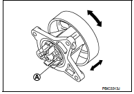
INSPECTION AFTER REMOVAL
• Check visually that there is no significant dirt or rusting on water pump body and vane (A).
• Check that there is no looseness in vane shaft, and that it turns smoothly when rotated by hand.
• Replace water pump, if necessary.
INSPECTION AFTER INSTALLATION
• Check for leakage of engine coolant using the radiator cap tester adapter (commercial service tool) and the radiator cap tester (commercial service tool). Refer to CO-11, "Inspection".
• Start and warm up the engine. Check visually that there is no leakage of engine coolant.
 Cooling fan
Exploded View
1. Fan motor
2. Fan shroud
3. Cooling fan
A. Apply on fan motor shaft
: N·m (kg-m, in-lb)
: Apply genuine high strength thread
locking sealant or equivalent.
Removal and In ...
 Thermostat
Exploded View
1. Thermostat housing
2. Gasket
3. Rubber ring
4. Thermostat
5. Water inlet
6. Clamp
7. Radiator hose (upper)
A. To radiator
Engine front
: N·m (kg-m, ft-lb)
: Always ...
Other materials:
Fuel level sensor unit, fuel filter
and fuel pump assembly
2WD : Exploded View
1. Fuel tank
2. Lock ring
3.
Fuel level sensor unit, fuel filter and
fuel pump assembly
4. Rock ring
Vehicle front
: N?·m (kg-m, ft-lb)
: Always replace after every
disassembly.
2WD : Removal and Installation
WARNING:
Read ???General Precautions??? when worki ...
Secondary speed sensor
Exploded View
1. Transaxle assembly
2. O-ring
3. Secondary speed sensor
: Vehicle front
: Always replace after every
disassembly.
: N·m (kg-m, in-lb)
: Genuine NISSAN CVT Fluid NS-2
Removal and Installation
REMOVAL
1. Disconnect battery cable from negative terminal. Refer to PG-124, ...
Lubricant
Description
MAINTENANCE OF LUBRICANT LEVEL
The compressor lubricant is circulating in the system together with the
refrigerant. It is necessary to fill compressor
with lubricant when replacing A/C system parts or when a large amount of
refrigerant leakage is
detected. It is important to alwa ...
