Nissan Juke Service and Repair Manual : Radiator
Exploded View
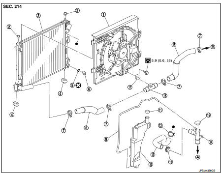
1. Cooling fan assembly
2. Mounting rubber (upper)
3. Radiator
4. Mounting rubber (lower)
5. O-ring 6. Drain plug
7. Clamp 8. Radiator hose (lower) (LH)
9. Reservoir tank hose
10. Reservoir tank
11. Reservoir tank cap
12. Clamp
13. Radiator hose (upper)
14. Water outlet adaptor
15. Radiator cap
16. Radiator hose pipe
17. Bracket
18. Radiator hose (lower) (RH)
A. To water outlet
B. To water inlet
 : N·m (kg-m, in-lb)
 : Always replace after every
disassembly.
Removal and Installation
REMOVAL
WARNING:
• Never remove radiator cap when engine is hot. Serious burns may occur from
high-pressure engine
coolant escaping from radiator.
• Wrap a thick cloth around the radiator cap. Slowly turn it a quarter of a turn to release built-up pressure.
Then turn it all the way.
1. Drain engine coolant from radiator. Refer to CO-11, "Draining".
CAUTION
:
• Perform this step when the engine is cold.
• Never spill engine coolant on drive belt.
2. Remove engine cover. Refer to EM-25, "Exploded View".
3. Remove engine under cover.
4. Remove radiator hose (upper and lower).
5. Remove front bumper. Refer to EXT-12, "Exploded View".
6. Remove radiator core support upper. Refer to DLK-149, "MR16DDT : Exploded View".
7. Disconnect cooling fan harness connector.
8. Remove reservoir tank.
9. Remove cooling fan assembly.
CAUTION:
Be careful not to damage or scratch the radiator core.
10. Remove condenser from radiator and temporarily fasten it on vehicle with a rope.
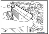
11. Pull up and remove the radiater assembly (1).
CAUTION:
Be careful not to damage radiator core and condenser
assembly core.
INSTALLATION
Install in the reverse order of removal.
INSTALLATION
Note the following, and install in the reverse order of removal.
NOTE
:
• Insert the radiator hose (1) all the way to the stopper (2) or by 33 mm (1.30 in) (hose without a stopper).
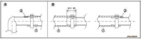
Unit mm (in)
A. Radiator side
B. Engine side
• For the orientation of the hose clamp pawl, refer to the figure.
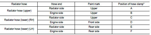
*Refer to the illustrations for the specific position each hose clamp tab.
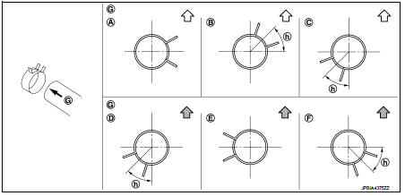
G. View
G h. 45°
 : Vehicle upper
 : Vehicle front
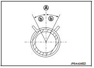
• The angle (b) created by the hose clamp pawl and the specified line (A) must be within ±15° as shown in the figure.
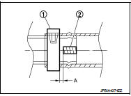
• To install hose clamps (1), check that the dimension (A) from the end of the paint mark (2) on the radiator hose to the hose clamp is within the reference value.
Dimension “A” 3 mm
Inspection
INSPECTION AFTER INSTALLATION
• Check for leakage of engine coolant using the radiator cap tester adapter (commercial service tool) and the radiator cap tester (commercial service tool). Refer to CO-11, "Inspection".
• Start and warm up the engine. Check visually that there is no leakage of engine coolant.

 Cooling fan
Exploded View
1. Fan motor
2. Fan shroud
3. Cooling fan
A. Apply on fan motor shaft
: N·m (kg-m, in-lb)
: Apply genuine high strength thread
locking sealant or equivalent.
Removal and In ...
Other materials:
B2628 outside antenna
DTC Logic
DTC DETECTION LOGIC
DTC CONFIRMATION PROCEDURE
1.PERFORM DTC CONFIRMATION PROCEDURE
1. Disconnect outside key antenna (rear bumper) connector.
2. Perform “INTELLIGENT KEY” Self Diagnostic Result.
Is outside key antenna DTC detected?
YES >> Refer to DLK-240, "Diagn ...
On Board Diagnostic (OBD) System of Engine
The ECM has an on board diagnostic system. It will light up the malfunction
indicator (MI) to warn the driver of
a malfunction causing emission deterioration.
CAUTION:
• Be sure to turn the ignition switch OFF and disconnect the battery negative
cable before any repair
or inspection work ...
Intelligent Around View Monitor
system limitations
WARNING
Listed below are the vital engineering system limitations for the Intelligent Around View Monitor.
Failure to operate your vehicle in strict accordance with these system limitations could blind the driver to surrounding hazards, which could result in ser ...
