Nissan Juke Service and Repair Manual : B1036 crash zone sensor
DTC Logic
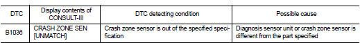
DTC DETECTION LOGIC
DTC CONFIRMATION PROCEDURE
1.CHECK SELF-DIAG RESULT
 With CONSULT-III
1. Turn ignition switch ON.
2. Perform ŌĆ£Self Diagnostic ResultŌĆØ mode of ŌĆ£AIR BAGŌĆØ using CONSULT-III.
 Without CONSULT-III
1. Turn ignition switch ON.
2. Check the air bag warning lamp status. Refer to SRC-12, "On Board Diagnosis Function".
NOTE
:
SRS does not enter the diagnosis mode if no malfunction is detected in the user
mode.
Is malfunctioning part detected? YES >> Refer to SRC-41, "Diagnosis Procedure".
NO >> INSPECTION END
Diagnosis Procedure
WARNING:
ŌĆó Before servicing, turn ignition switch OFF, disconnect battery negative
terminal, and wait 3 minutes
or more. (To discharge backup capacitor.)
ŌĆó Never use unspecified tester or other measuring device.
1.CHECK HARNESS CONNECTOR
Check the harness connector.
Is the inspection result normal? YES >> GO TO 2.
NO >> Replace harness connectors.
2.CHECK WIRING HARNESS
Check the wiring harness externals.
Is the inspection result normal? YES >> GO TO 3.
NO >> Replace wiring harness.
3.REPLACE CRASH ZONE SENSOR
1. Replace crash zone sensor. Refer to SR-26, "Removal and Installation".
2. Perform DTC confirmation procedure. Refer to SRC-41, "DTC Logic".
Is DTC detected? YES >> GO TO 4.
NO >> INSPECTION END
4.REPLACE AIR BAG DIAGNOSIS SENSOR UNIT
1. Replace air bag diagnosis sensor unit. Refer to SR-30, "Removal and Installation".
2. Perform DTC confirmation procedure. Refer to SRC-41, "DTC Logic".
Is DTC detected? YES >> GO TO 1.
NO >> INSPECTION END
 B1035 crash zone sensor
DTC Logic
DTC DETECTION LOGIC
DTC CONFIRMATION PROCEDURE
1.CHECK SELF-DIAG RESULT
With CONSULT-III
1. Turn ignition switch ON.
2. Perform ŌĆ£Self Diagnostic ResultŌĆØ mode of ŌĆ£AIR BAGŌĆØ usi ...
 B1037, B1039, B1041 crash zone sensor
DTC Logic
DTC DETECTION LOGIC
DTC CONFIRMATION PROCEDURE
1.CHECK SELF-DIAG RESULT
With CONSULT-III
1. Turn ignition switch ON.
2. Perform ŌĆ£Self Diagnostic ResultŌĆØ mode of ŌĆ£AIR BAGŌĆØ usi ...
Other materials:
B2321, B2322 oil level sensor
Description
The oil level sensor detects the level of engine oil, and then transmits the
oil level signal to the combination
meter.
DTC Logic
DTC DETECTION LOGIC
NOTE:
When the following conditions are satisfied, the combination meter reads the
resistance value of oil level sensor.
Th ...
Manual Transmission (MT)
The ignition switch includes a device that helps prevent accidental removal of
the key while driving.
The key can only be removed when the ignition switch is in the LOCK position.
To turn the ignition switch to the LOCK position from the ACC or ON position,
turn the key to the OFF position, ...
Key warning lamp
Component Function Check
1.CHECK FUNCTION
1. Select ŌĆ£INTELLIGENT KEYŌĆØ of ŌĆ£BCMŌĆØ using CONSULT-III.
2. Select ŌĆ£INDICATORŌĆØ in ŌĆ£ACTIVE TESTŌĆØ mode.
3. Check that the function operates normally according to the following
conditions.
Is the inspection result normal?
YES >> K ...
