Nissan Juke Service and Repair Manual : C1155 brake fluid level switch
DTC Logic
DTC DETECTION LOGIC
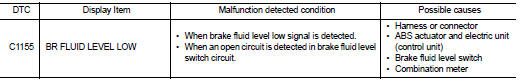
DTC CONFIRMATION PROCEDURE
1.PRECONDITIONING
If “DTC CONFIRMATION PROCEDURE” has been previously conducted, always turn ignition switch OFF and wait at least 10 seconds before conducting the next test.
>> GO TO 2.
2.CHECK DTC DETECTION
 With CONSULT-III.
1. Turn the ignition switch OFF to ON.
2. Perform self-diagnosis for “ABS”.
Is DTC “C1155” detected? YES >> Proceed to BRC-192, "Diagnosis Procedure".
NO >> INSPECTION END
Diagnosis Procedure
1.CHECK BRAKE FLUID LEVEL
1. Turn the ignition switch OFF.
2. Check brake fluid level.
- LHD: Refer to BR-12, "Inspection".
- RHD: Refer to BR-80, "Inspection".
Is the inspection result normal? YES >> GO TO 2.
NO >> Refill brake fluid.
• LHD: Refer to BR-12, "Refilling".
• RHD: Refer to BR-80, "Refilling".
2.PERFORM SELF-DIAGNOSIS (1)
With CONSULT-III.
1. Erase Self-diagnosis result for “ABS”.
2. Turn the ignition switch OFF, and wait 10 seconds or more.
3. Turn the ignition switch ON.
CAUTION:
Never start the engine.
4. Perform self-diagnosis for “ABS”.
Is DTC “C1155” detected? YES >> INSPECTION END
NO >> GO TO 3.
3.CHECK BRAKE FLUID LEVEL SWITCH
Check brake fluids level switch. Refer to BRC-194, "Component Inspection".
Is the inspection result normal?
YES >> GO TO 5.
NO >> Replace reservoir tank. GO TO 4.
• LHD: Refer to BR-44, "Disassembly and Assembly".
• RHD: Refer to BR-109, "Disassembly and Assembly".
4.PERFORM SELF-DIAGNOSIS (2)
With CONSULT-III.
1. Erase Self-diagnosis result for “ABS”.
2. Turn the ignition switch OFF, and wait 10 seconds or more.
3. Turn the ignition switch ON.
CAUTION:
Never start the engine.
4. Perform self-diagnosis for “ABS”.
Is DTC “C1155” detected? YES >> INSPECTION END
NO >> GO TO 5.
5.CHECK CONNECTOR AND TERMINAL
1. Turn the ignition switch OFF.
2. Disconnect brake fluid level switch harness connector.
3. Check brake fluid level switch harness connector for disconnection or looseness.
4. Check brake fluid level switch pin terminals for damage or loose connection with harness connector.
5. Disconnect combination meter harness connector.
6. Check combination meter harness connector for disconnection or looseness.
7. Check combination meter pin terminals for damage or loose connection with harness connector.
Is the inspection result normal? YES >> GO TO 7.
NO >> Repair or replace error-detected parts. GO TO 6.
6.PERFORM SELF-DIAGNOSIS (3)
With CONSULT-III.
1. Connect brake fluid level switch harness connector.
2. Connect combination meter harness connector.
3. Erase Self-diagnosis result for “ABS”.
4. Turn the ignition switch OFF, and wait 10 seconds or more.
5. Turn the ignition switch ON.
CAUTION:
Never start the engine.
6. Perform self-diagnosis for “ABS”.
Is DTC “C1155” detected? YES >> INSPECTION END
NO >> GO TO 7.
7.CHECK BRAKE FLUID LEVEL SWITCH HARNESS
1. Turn the ignition switch OFF.
2. Disconnect brake fluid level switch harness connector.
3. Disconnect combination meter harness connector.
4. Check continuity between brake fluid level switch harness connector and combination meter harness connector.
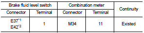
*1: 4WD
*2: 2WD
5. Check continuity between brake fluid level switch harness connector and ground.
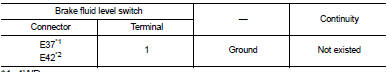
*1: 4WD
*2: 2WD
Is the inspection result normal? YES >> GO TO 8.
NO >> Repair or replace error-detected parts. GO TO 8.
8.CHECK BRAKE FLUID LEVEL SWITCH GROUND
Check continuity between brake fluid level switch harness connector and ground.
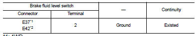
*1: 4WD
*2: 2WD
Is the inspection result normal? YES >> GO TO 9.
NO >> Repair or replace error-detected parts. GO TO 9.
9.CHECK COMBINATION METER
Check combination meter. Refer to MWI-23, "CONSULT-III Function".
Is the inspection result normal? YES >> Replace ABS actuator and electric unit (control unit). Refer to BRC-233, "Removal and Installation".
NO >> Repair or replace combination meter. Refer to MWI-69, "Removal and Installation".
Component Inspection
1.CHECK BRAKE FLUID LEVEL SWITCH
1. Turn the ignition switch OFF.
2. Disconnect brake fluid level switch harness connector.
3. Check continuity between terminals of brake fluid level switch.
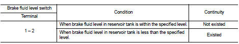
Is the inspection result normal? YES >> INSPECTION END
NO >> Replace reservoir tank.
• LHD: Refer to BR-44, "Disassembly and Assembly".
• RHD: Refer to BR-109, "Disassembly and Assembly".
 C1144 incomplete steering angle sensor adjustment
DTC Logic
DTC DETECTION LOGIC
DTC CONFIRMATION PROCEDURE
1.PRECONDITIONING
If “DTC CONFIRMATION PROCEDURE” has been previously conducted, always turn
ignition switch OFF and
wait at least ...
 C1164, C1165 CV system
DTC Logic
DTC DETECTION LOGIC
DTC CONFIRMATION PROCEDURE
1.PRECONDITIONING
If “DTC CONFIRMATION PROCEDURE” has been previously conducted, always turn
ignition switch OFF and
wait at least ...
Other materials:
Symptom diagnosis
Squeak and rattle trouble diagnoses
Work Flow
CUSTOMER INTERVIEW
Interview the customer if possible, to determine the conditions that exist
when the noise occurs. Use the Diagnostic
Worksheet during the interview to document the facts and conditions when the
noise occurs and any of
the cu ...
Check anti-pinch function
Description
If any of the following operations are performed, the initialization is
necessary for normal operation of antipinch
function.
• Disconnection and connection of battery cable from negative terminal.
• When power window main switch replaced.
• Electric power supply to power ...
High voltage precautions
High-voltage components
WARNING
The advanced electric vehicle (EV) system in your Nissan Leaf operates using high-voltage electricity, reaching levels up to approximately 400 volts DC. Please be aware that these internal components can remain extremely hot during operation, immed ...
