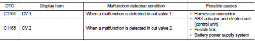
Nissan Juke Service and Repair Manual : C1164, C1165 CV system
DTC Logic
DTC DETECTION LOGIC
DTC CONFIRMATION PROCEDURE
1.PRECONDITIONING
If “DTC CONFIRMATION PROCEDURE” has been previously conducted, always turn ignition switch OFF and wait at least 10 seconds before conducting the next test.
>> GO TO 2.
2.CHECK DTC DETECTION
 With CONSULT-III.
1. Turn the ignition switch OFF to ON.
2. Perform self-diagnosis for “ABS”.
Is DTC “C1164” or “C1165” detected? YES >> Proceed to BRC-195, "Diagnosis Procedure".
NO >> INSPECTION END
Diagnosis Procedure
1.CHECK CUT VALVE POWER SUPPLY
1. Turn the ignition switch OFF.
2. Disconnect ABS actuator and electric unit (control unit) harness connector.
3. Check voltage between ABS actuator and electric unit (control unit) harness connector and ground.
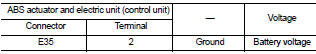
4. Turn the ignition switch ON.
CAUTION:
Never start engine.
5. Check voltage between ABS actuator and electric unit (control unit) harness connector and ground.
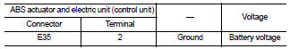
Is the inspection result normal? YES >> GO TO 3.
NO >> GO TO 2.
2.CHECK CUT VALVE POWER SUPPLY CIRCUIT
1. Turn the ignition switch OFF.
2. Check 50 A fusible link (I).
3. Check continuity and short circuit between ABS actuator and electric unit (control unit) harness connector terminal (2) and 50 A fusible link (I).
Is the inspection result normal? YES >> Perform trouble diagnosis for battery power supply. Refer to PG-10, "Wiring Diagram - BATTERY POWER SUPPLY -".
NO >> Repair or replace error-detected parts.
3.CHECK CUT VALVE GROUND CIRCUIT
1. Turn the ignition switch OFF.
2. Check continuity between ABS actuator and electric unit (control unit) harness connector and the ground.
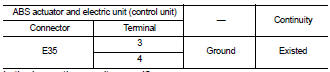
Is the inspection result normal? YES >> GO TO 4.
NO >> Repair or replace error-detected parts.
4.CHECK TERMINAL
Check ABS actuator and electric unit (control unit) pin terminals for damage or loose connection with harness connector.
Is the inspection result normal? YES >> Replace ABS actuator and electric unit (control unit). Refer to BRC-233, "Removal and Installation".
NO >> Repair or replace error-detected parts.
 C1155 brake fluid level switch
DTC Logic
DTC DETECTION LOGIC
DTC CONFIRMATION PROCEDURE
1.PRECONDITIONING
If “DTC CONFIRMATION PROCEDURE” has been previously conducted, always turn
ignition switch OFF and
wait at least ...
 C1166, C1167 SV system
DTC Logic
DTC DETECTION LOGIC
DTC CONFIRMATION PROCEDURE
1.PRECONDITIONING
If “DTC CONFIRMATION PROCEDURE” has been previously conducted, always turn
ignition switch OFF and
wait at least ...
Other materials:
Precaution for Supplemental Restraint System (SRS) "AIR BAG" and "SEAT BELT
PRE-TENSIONER"
The Supplemental Restraint System such as ???AIR BAG??? and ???SEAT BELT PRE-TENSIONER???,
used along
with a front seat belt, helps to reduce the risk or severity of injury to the
driver and front passenger for certain
types of collision. This system includes seat belt switch inputs and dual s ...
Camshaft
*: Total indicator reading
Valve Lifter
Valve Clearance
*:Approximately 80°C (176°F)
Available Valve Lifter
...
RCTA system operation
Side Indicator Light
The RCTA system acts as an extra set of eyes, helping to alert the driver to approaching traffic while reversing out of a parking stall or driveway.
The system becomes active when the shift position is set to R (Reverse) ...
