Nissan Juke Service and Repair Manual : C1166, C1167 SV system
DTC Logic
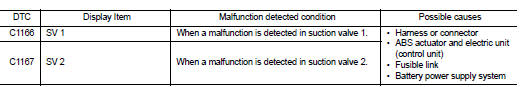
DTC DETECTION LOGIC
DTC CONFIRMATION PROCEDURE
1.PRECONDITIONING
If ŌĆ£DTC CONFIRMATION PROCEDUREŌĆØ has been previously conducted, always turn ignition switch OFF and wait at least 10 seconds before conducting the next test.
>> GO TO 2.
2.CHECK DTC DETECTION
 With CONSULT-III.
1. Turn the ignition switch OFF to ON.
2. Perform self-diagnosis for ŌĆ£ABSŌĆØ.
Is DTC ŌĆ£C1166ŌĆØ or ŌĆ£C1167ŌĆØ detected? YES >> Proceed to BRC-197, "Diagnosis Procedure".
NO >> INSPECTION END
Diagnosis Procedure
1.CHECK CUT VALVE POWER SUPPLY
1. Turn the ignition switch OFF.
2. Disconnect ABS actuator and electric unit (control unit) harness connector.
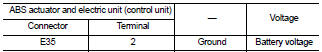
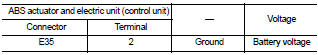
3. Check voltage between ABS actuator and electric unit (control unit) harness connector and ground.
4. Turn the ignition switch ON.
CAUTION:4. Turn the ignition switch ON.
CAUTION: Never start engine.
5. Check voltage between ABS actuator and electric unit (control unit) harness connector and ground.
Never start engine.
5. Check voltage between ABS actuator and electric unit (control unit) harness connector and ground.
Is the inspection result normal? YES >> GO TO 3.
NO >> GO TO 2.
2.CHECK CUT VALVE POWER SUPPLY CIRCUIT
1. Turn the ignition switch OFF.
2. Check 50 A fusible link (I).
3. Check continuity and short circuit between ABS actuator and electric unit (control unit) harness connector terminal (2) and 50 A fusible link (I).
Is the inspection result normal? YES >> Perform trouble diagnosis for battery power supply. Refer to PG-10, "Wiring Diagram - BATTERY POWER SUPPLY -".
NO >> Repair or replace error-detected parts.
3.CHECK CUT VALVE GROUND CIRCUIT
1. Turn the ignition switch OFF.
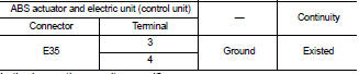
2. Check continuity between ABS actuator and electric unit (control unit) harness connector and the ground
Is the inspection result normal? YES >> GO TO 4.
NO >> Repair or replace error-detected parts.
4.CHECK TERMINAL
Check ABS actuator and electric unit (control unit) pin terminals for damage or loose connection with harness connector.
Is the inspection result normal? YES >> Replace ABS actuator and electric unit (control unit). Refer to BRC-233, "Removal and Installation".
NO >> Repair or replace error-detected parts.
 C1164, C1165 CV system
DTC Logic
DTC DETECTION LOGIC
DTC CONFIRMATION PROCEDURE
1.PRECONDITIONING
If ŌĆ£DTC CONFIRMATION PROCEDUREŌĆØ has been previously conducted, always turn
ignition switch OFF and
wait at least ...
 C1176 stop lamp SW2
DTC Logic
DTC DETECTION LOGIC
DTC CONFIRMATION PROCEDURE
1.PRECONDITIONING
If ŌĆ£DTC CONFIRMATION PROCEDUREŌĆØ has been previously conducted, always turn
ignition switch OFF and
wait at least ...
Other materials:
Manual Transmission (MT)
The ignition switch includes a device that helps prevent accidental removal of
the key while driving.
The key can only be removed when the ignition switch is in the LOCK position.
To turn the ignition switch to the LOCK position from the ACC or ON position,
turn the key to the OFF position, ...
Component parts
Component Parts Location
ENGINE ROOM COMPARTMENT
Top View
1. Priming pump
2. Turbocharger boost control solenoid
valve
3. Cooling fan motor
4. Refrigerant pressure sensor
5. IPDM E/R
6. ECM
7. Mass air flow sensor (with intake air
temperature sensor)
8. Electric throttle control act ...
Diagnosis and repair work flow
Work Flow
OVERALL SEQUENCE
DETAILED FLOW
1.GET INFORMATION FOR SYMPTOM
1. Get the detailed information from the customer about the symptom (the
condition and the environment
when the incident/malfunction occurred).
2. Check operation condition of the function that is malfunctioning.
> ...
