Nissan Juke Service and Repair Manual : C1176 stop lamp SW2
DTC Logic
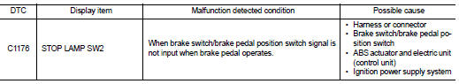
DTC DETECTION LOGIC
DTC CONFIRMATION PROCEDURE
1.PRECONDITIONING
If “DTC CONFIRMATION PROCEDURE” has been previously conducted, always turn ignition switch OFF and wait at least 10 seconds before conducting the next test.
>> GO TO 2.
2.CHECK DTC DETECTION
 With CONSULT-III.
1. Turn the ignition switch OFF to ON.
2. Perform self-diagnosis for “ABS”.
Is DTC “C1176” detected? YES >> Proceed to BRC-199, "Diagnosis Procedure".
NO >> INSPECTION END
Diagnosis Procedure
NOTE
:
DTC “C1176” may be detected when the brake pedal and the accelerator pedal are
simultaneously depressed
for 1 minute or more while driving the vehicle. This is not a malfunction.
1.INTERVIEW FROM THE CUSTOMER
Check if the brake pedal and the accelerator pedal are simultaneously depressed for 1 minute or more while driving the vehicle.
Is there such a history? YES >> GO TO 2.
NO >> GO TO 3.
2.PERFORM SELF-DIAGNOSIS
 With CONSULT-III.
1. Erase Self-diagnosis result for “ABS”.
2. Turn the ignition switch OFF, and wait 10 seconds or more.
3. Start the engine.
CAUTION:
Never start the vehicle.
4. Depress the brake pedal several times.
5. Perform self-diagnosis for “ABS”.
Is DTC “C1176” detected? YES >> GO TO 3.
NO >> INSPECTION END
3.CHECK BRAKE SWITCH/BRAKE PEDAL POSITION SWITCH CLEARANCE
1. Turn the ignition switch OFF.
2. Check brake switch/brake pedal position switch clearance.
- LHD: Refer to BR-9, "Inspection and Adjustment".
- RHD: Refer to BR-77, "Inspection and Adjustment".
Is the inspection result normal? YES >> GO TO 5.
NO >> Adjust brake switch/brake pedal position switch clearance. GO TO 4.
• LHD: Refer to BR-77, "Inspection and Adjustment".
• RHD: Refer to BR-77, "Inspection and Adjustment".
4.CHECK DATA MONITOR (1)
 With CONSULT-III.
1. Erase Self-diagnosis result for “ABS”.
2. Turn the ignition switch OFF, and wait 10 seconds or more.
3. Start the engine.
CAUTION:
Never start the vehicle.
4. Select “ABS”, “DATA MONITOR” and “STOP LAMP SW2” according to this order. Check that data monitor displays “On” or “Off” when brake pedal is depress or release. Refer to BRC-136, "Reference Value".
Is the inspection result normal? YES >> INSPECTION END
NO >> GO TO 5.
5.CHECK BRAKE SWITCH/BRAKE PEDAL POSITION SWITCH
Check brake switch/brake pedal position switch. Refer to BRC-177, "Component Inspection".
Is the inspection result normal? YES >> GO TO 7.
NO >> Replace brake switch/brake pedal position switch. GO TO 6.
• LHD: Refer to BR-21, "Removal and Installation".
• RHD: Refer to BR-89, "Removal and Installation".
6.CHECK DATA MONITOR (2)
 With CONSULT-III.
1. Erase Self-diagnosis result for “ABS”.
2. Turn the ignition switch OFF, and wait 10 seconds or more.
3. Start the engine.
CAUTION:
Never start the vehicle.
4. Select “ABS”, “DATA MONITOR” and “STOP LAMP SW2” according to this order. Check that data monitor displays “On” or “Off” when brake pedal is depress or release. Refer to BRC-136, "Reference Value".
Is the inspection result normal? YES >> INSPECTION END NO >> GO TO 7.
7.CHECK CONNECTOR AND TERMINAL
1. Turn the ignition switch OFF.
2. Disconnect ABS actuator and electric unit (control unit) harness connector.
3. Check ABS actuator and electric unit (control unit) harness connector for disconnection or looseness.
4. Check ABS actuator and electric unit (control unit) pin terminals for damage or loose connection with harness connector.
5. Disconnect brake switch/brake pedal position switch harness connector.
6. Check brake switch/brake pedal position switch harness connector for disconnection or looseness.
7. Check brake switch/brake pedal position switch pin terminals for damage or loose connection with harness connector.
Is the inspection result normal? YES >> GO TO 9.
NO >> Repair or replace error-detected parts. GO TO 8.
8.CHECK DATA MONITOR (3)
 With CONSULT-III.
1. Connect ABS actuator and electric unit (control unit) harness connector.
2. Connect brake switch/brake pedal position switch harness connector.
3. Erase Self-diagnosis result for “ABS”.
4. Turn the ignition switch OFF, and wait 10 seconds or more.
5. Start the engine.
CAUTION:
Never start the vehicle.
6. Select “ABS”, “DATA MONITOR” and “STOP LAMP SW2” according to this order. Check that data monitor displays “On” or “Off” when brake pedal is depress or release. Refer to BRC-136, "Reference Value".
Is the inspection result normal? YES >> INSPECTION END
NO >> GO TO 11.
9.CHECK BRAKE SWITCH/BRAKE PEDAL POSITION SWITCHCIRCUIT (1)
1. Turn the ignition switch OFF.
2. Disconnect ABS actuator and electric unit (control unit) harness connector.
3. Check voltage between ABS actuator and electric unit (control unit) harness connector and ground.

4. Turn the ignition switch ON.
5. Check voltage between ABS actuator and electric unit (control unit) harness connector and ground.
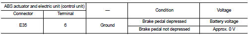
Is the inspection result normal? YES >> Replace ABS actuator and electric unit (control unit). Refer to BRC-233, "Removal and Installation".
NO >> Repair or replace error-detected parts. GO TO 10.
10.CHECK BRAKE SWITCH/BRAKE PEDAL POSITION SWITCH CIRCUIT (2)
1. Turn the ignition switch OFF.
2. Disconnect brake switch/brake pedal position switch harness connector.
3. Check continuity between ABS actuator and electric unit (control unit) harness connector and brake switch/brake pedal position switch harness connector.
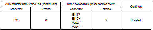
*1: Brake switch (LHD models and RHD models with CVT) *2: Brake pedal position switch (LHD models and RHD models with CVT) *3: Brake switch (RHD models with M/T) *4: Brake pedal position switch (RHD models with M/T)
4. Check continuity between ABS actuator and electric unit (control unit) harness connector and the ground.
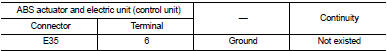
Is the inspection result normal? YES >> Replace ABS actuator and electric unit (control unit). Refer to BRC-233, "Removal and Installation".
NO >> Repair or replace error-detected parts. GO TO 11.
11.CHECK DATA MONITOR (4)
With CONSULT-III.
1. Connect ABS actuator and electric unit (control unit) harness connector.
2. Connect brake switch/brake pedal position switch harness connector.
3. Erase Self-diagnosis result for “ABS”.
4. Turn the ignition switch OFF, and wait 10 seconds or more.
5. Start the engine.
CAUTION:
Never start the vehicle.
6. Select “ABS”, “DATA MONITOR” and “STOP LAMP SW2” according to this order. Check that data monitor displays “On” or “Off” when brake pedal is depress or release. Refer to BRC-136, "Reference Value".
Is the inspection result normal? YES >> INSPECTION END
NO >> Replace ABS actuator and electric unit (control unit). Refer to BRC-233, "Removal and Installation".
Component Inspection
1.CHECK BRAKE SWITCH/BRAKE PEDAL POSITION SWITCH
1. Turn ignition switch OFF.2. Disconnect brake switch/brake pedal position switch harness connector.
3. Check continuity between brake switch/brake pedal position switch harness connector terminals.
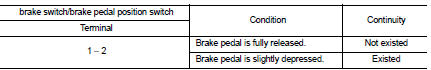
Is the inspection result normal? YES >> INSPECTION END
NO >> Replace brake switch/brake pedal position switch.
• LHD: Refer to BR-21, "Removal and Installation".
• RHD: Refer to BR-89, "Removal and Installation".
 C1166, C1167 SV system
DTC Logic
DTC DETECTION LOGIC
DTC CONFIRMATION PROCEDURE
1.PRECONDITIONING
If “DTC CONFIRMATION PROCEDURE” has been previously conducted, always turn
ignition switch OFF and
wait at least ...
 U1000 can comm circuit
Description
CAN (Controller Area Network) is a serial communication line for real time
application. It is an on-vehicle multiplex
communication line with high data communication speed and excellen ...
Other materials:
Starting difficult with cold engine
Description
CHART 3: STARTING DIFFICULT WITH COLD ENGINE
Diagnosis Procedure
1.CHECK ENGINE OIL LEVEL
Is the engine oil level correct?
Yes or No
Yes >> GO TO 2.
No >> Top up the oil.
2.CHECK ENGINE OIL
Check the grade of engine oil. Refer to LU-33, "Inspection".
...
Oil pan (lower)
Exploded View
1. O-ring
2. Oil pan (upper)
3. Oil level gauge guide
4. O-ring
5. Oil level gauge
6. Oil pump drive chain
7. Crankshaft sprocket
8. Oil pump sprocket
9. Oil pump chain tensioner
10. Oil pump
11. Drain plug
12. Drain plug washer
13. Oil pan (lower)
14. Oil fil ...
Drive pinion
Exploded View
1. Filler plug
2. Gasket
3. Drain plug
4. Breather tube
5. Clip
6. Breather hose
7. Breather
8. sub-harness clip
9. sub-harness
10. Rear cover
11. Center stem
12. Side bearing (right)
13. Side bearing adjusting shim (right)
14. Side oil seal (right)
15. Conne ...
